|
Home Updates Hydros Cars Engines Contacts Links ←Previous Aircar article Contact On The Wire |
|
|
Steve Betney's Work Bench |
COOPER CLIMAX T60 1962 DIESEL RAIL CAR
|
|
Now, this little car wasn’t even part of my projects’ WIP pile or even a glint in my eye before the Old Warden Mayfly event a couple of months ago, but it has somehow jumped to the head of my production schedule and been finished already, and is back to my F1 type of subject, albeit a rail car rather than tethered this time. Having stopped for my customary chat with Bill and Pat Langley by Bill’s portable oval rail racing track near the old compass circle at Old Warden, and seeing a variety of his diesel rail cars rotating as usual at various speeds, up to 3 at a time, I decided that I really had to have something to run at future OW events to keep Bill company. He informed me that he has constructed an even larger, 4-rail figure of 8 track layout which he plans to use in future, so there will be room for more cars presenting an even more impressive spectacle, so I decided to make a car to join in, hopefully at OW Scale Weekend. |
After a long root through my car parts’ stock, I came up with an old, used MRRC aluminium chassis casting for 1.0 to 1.5cc engines as a basis, procured a while ago on eBay. This had the cast-in engine mounting blocks already drilled, and an AM 15 fitted these exactly. An AM 10 would be better suited to the track, but I only had a 15 to hand so will start with that whilst I look out for a decent 10. The position of the engine, and most particularly its cylinder head, which was just about exactly half way between the front & rear axles, dictated the choice of full size subject to model, so that the head would be in the open cockpit area. This excludes many vintage front engine F1 cars which have the cockpit and driver closer to the back axle, and even many more modern rear engine cars, which also have the problem of not suiting the MRRC chassis shape.
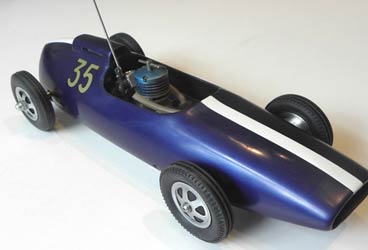
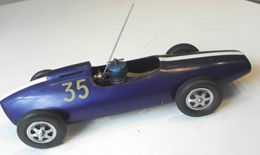
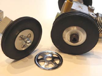
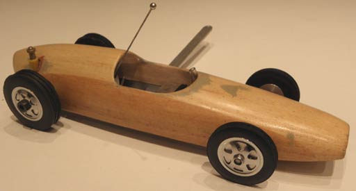
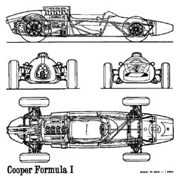
A long web search came up with the 1960s Cooper Climax car as a suitable and quite attractive candidate, and in particular the 1962 T60 1.5 litre model driven by Bruce McLaren, which has an interesting looking cowl over the cylinder heads and carbs just behind the driver’s head, and also an unusually shaped open rear end. A 3-view drawing was located and then scaled to suit the 7.75" wheelbase of the chassis, so the plan and side elevation outlines of the body were defined. Repro Raylite 2.25" tyres are a suitable scale for the rear, drive wheels, and similar diameter repro Peri & Rice tyres were selected for the front for their narrower tread and scale appearance. I found some nice pressed metal hubcaps which fit both of these tyre types at toydecals.com in the USA, ERTL type ETP-001 at $13 plus postage for a set of 4, and these add a nice touch to the appearance of the finished wheels and model, though they are not strictly the correct spoke pattern. A further root around my parts’ stock came up with a suitable modern RC flywheel and clutch assembly, a set of 2:1 bevel gears, 3 MRA 5mm bearing housings, an old c/l team race fuel tank and a 13" long block of hard balsa wood, so a kit was to hand.
 |
 |
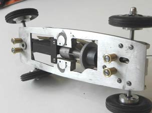
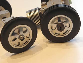
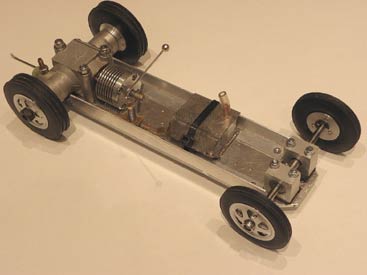
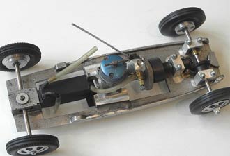
The images show the layout of the model, which has a swivelling front axle simply because the base MRRC chassis had used one, so the front mounting block on the casting was already drilled and slotted for this configuration, and I just cleaned it up and used a pair of flanged ball bearings to mount the swivelling pillar for the 5mm axle.
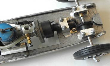
The aluminium wheels turned up for the Peri & Rice front tyres have deep groove 5mm ball bearings inboard and thin, sintered bronze sleeves to the outside. The 5mm rear, driven axle is mounted in two MRA bearing blocks, and the 5mm pinion bevel gear drive shaft supported in a 3rd MRA housing, as can be seen from the image of the finished chassis. I wanted to have a fuel cut out on the AM engine rather than rely on running out the tank each time on the track, so I modified a small RC throttle I had spare (I don’t remember its origin) with a wire "sneaker" arm added. This is Araldited into the venturi, and a couple of small blanking plugs similarly fixed into the spraybar mounting holes to seal them off.
|
|
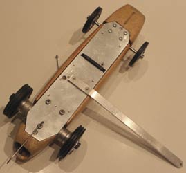
It took a surprisingly long time to make up the 4 rotating rail guides or zonkers, using information from Jim Elsegood’s published article in an old old Retro Racing Club Newsletter, as these have to be made to quite close tolerances and be free to rotate easily on their internal bearing surfaces (see the image of the underneath of the chassis). Bill Langley and Jim have found from experience that a pair of zonkers located just in front of both the front & rear axle at the centre line of the car work very well, and are much simpler to make than the vintage MRRC pivoting plate designs. If you want a copy of these instructions, please email me at stevebetney(at)aol.com and I’ll send you the info. |
|
The balsa body was designed to use internal 1/16" by ¾" aluminium strip side rails epoxy glued into its inside bottom edges, so that it could be fixed with four 6BA screws through the sides of the body into the tapped holes on the 4 lugs cast on the edges of the MRRC chassis for this purpose. After ensuring that the bare chassis plate snugly fitted in this way into a carefully excavated recess in the hard balsa wood body blank, the body plan and side profiles were drawn and the block band-sawed to shape. Then the part I like the most, carving and sanding the body to final external shape, followed by the less favoured internal excavation, and my least favourite final finishing stage. I used flexible weave 2oz glass cloth applied both externally and internally using Z Poxy resin, then multiple coats of cellulose sanding sealer and Imperial Blue cellulose spray paint and some final coats of fuel proofer (horrible job, it went badly yet again and took 4 rubbed down brushed layers I’m sad to report). |
|
|
|
I gave the car the racing number 35, as a nod to our SAM 35 society, which has just voted at the recent AGM to include vintage and sports style tethered (and rail) cars in our scope of modelling activities. Come and join us (go to sam35.org.uk), the monthly SAM 35 Speaks magazine with some colour content is worth much more than the membership fee, and it will include at least the occasional tethered car content |
NOTHING TO GET STEAMED UP ABOUT, STANLEY!
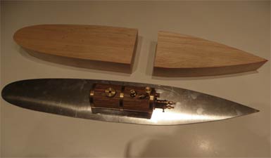
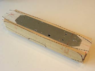
About 5 years ago I was looking for an unusual subject for a tethered car model to run on Peter Hill’s RRC track, and the 1906 Stanley Rocket, land speed record holding car caught my eye. Another fine mess you’ve gotten me into, Stanley! This car did 126.77mph in the USA running at 800-900psi steam pressure fired by petrol, and in 1907 with the pressure upped to 1300psi it crashed at around 150mph, with the driver mercifully and miraculously surviving. Nerves as well as cajones of steel (asbestos insulated)! The top of this amazing car was actually a very lightweight structure made by a canoe manufacturer, which rather shows in the appearance. I shan’t do a detailed description of the build for this car as it is unlikely that anyone else will be daft enough to want to make a similar model, but I’ll just describe a few of the main aspects here. The images should hopefully show most of the components and methods used. The model is built to 1/8 scale, with all dimensions derived from a drawing found on the web, which results in a 24 inch overall length.
|
|
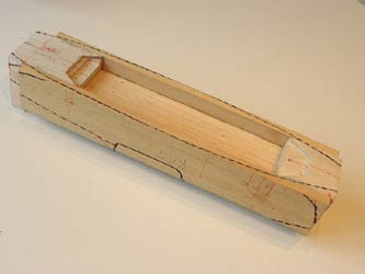
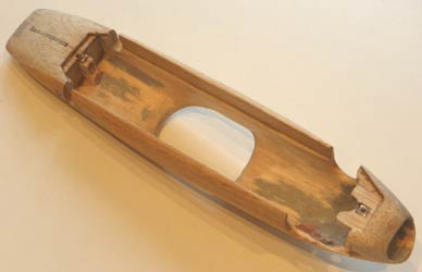
Construction starts on a 4mm aluminium plate sawn to shape as shown left, and the top "canoe" is shaped from two blocks of rock hard balsa, band sawn to shape. The boiler is a nice 2 inches diameter by 5 inches long item, which runs at 45psi maximum pressure and will supply enough steam after heating up for several minutes running time on the track. The whole concept of the model is made possible by using a twin shaft steam engine designed for model boats, and a very nice machined kit for the Cleveland Steam Virgo Paddle Steamer engine was made up to provide the motive force, with stub extension shafts turned up to achieve the desired 6.75 inches track. |
|
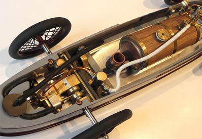
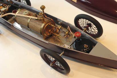
A BIX 62cc LPG tank supplies the gas to the boiler’s burner, and an RC servo gas shut off valve is fitted in the line so that a sneaker arm attached to this can be used as a cut off on the track. A condenser tank is fitted at the rear end so that excess steam vapour containing waste steam oil is not vented onto the track. 40 spoke wheels were used on the original car, and they look pretty spindly for running at 150 mph, but they did the job. Herbie Wheels in Germany make good quality and strong 40 spoke wheels intended for WW1 period scale model aircraft, and a set of four of the 105mm diameter types were procured, and really look the part on the finished model. A scale track speed of about 18mph should be achieved with this wheel size, with not too great a G force on the centre pylon with the hefty finished model weight of about 6 pounds. |
|
|
|
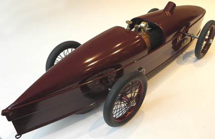
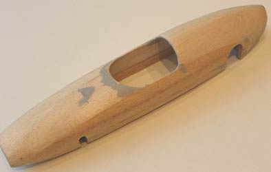
After planning the layout of the main components on the 4mm ali base plate, the body sides were built up from aluminium strip and 2mm plywood, and the top body formed by gluing the two top blocks together with formed 3/4" x 3/32" aluminium strip edges which overlap the top edges of the base sides. The top is retained by strong magnets at the front and rear ends. Kaowool insulation is used on all exposed interior body areas. Finish is in Ford Imperial Maroon cellulose spray, a very close match to the original colour, and the build time amounted to around 300 hours in total, much of this consumed getting a decent finish. I’m afraid that this car will be a shelf queen, (shame) as despite being engineered to be totally practical to run on the track, the necessary preparation time at the track side and general fiddling about would probably exceed my attention span these days, and also that of most other RRC track users too. |
COME IN, NUMBER 35
The outline specification for the new class of simple, direct drive (no gears) tethered cars for 2019 was proposed by Peter Hill in the final RRC Newsletter number 70. The easy way to participate in this class would be to procure one of the many 2.5cc Russian cars or School Car kits which appear for sale on eBay, but I have decided to build an example to show the design parameters for such a car so that anyone with good modelling skills can see how it is possible to put one together.
The main rules for this class covered the engine capacity limit of 2.5 cc, of either single (aero type) or twinshaft configuration with no gears, and the somewhat simpler of these options is a twinshaft engine with its drive wheels supplied, so I’ve used one of these. The Russian RYTM or TEMP twinshaft engines with their 55mm diameter drive wheels are fairly readily available and not too expensive. Some of these are offered together with the parts to make up a pair of front wheels with sprung axle parts too. One friendly eBay vendor in Latvia, Pavel Pirov (p12man), who has 3 generations of tethered car modellers in his family can usually supply such items, and has been very easy, helpful and reasonable to deal with in my experience, so try asking him at pps61@inbox.lv, or trawl eBay & the swapmeets to see if you can get one. If you’re lucky, you might get a repro CS Tiger or other twinshaft diesel such as a Rustler Tiger or Jaguar, but these are getting hard to find these days. An original Ollie twinshaft is just about unobtanium. We are hoping to eventually find a new supply of quality twinshaft engines, so this situation may ease in the future.
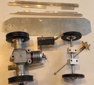
The image below shows all of the components of the rolling chassis for this design, and general ranges of dimensions for the layout will be suggested below, so that you can make the car body to any suitable shape that you wish, that will fit over the components, near scale or freestyle.
|
|
The track of the twinshaft engine dictates much of the design, and this is 100mm (wheel centre to centre) for the RYTM and TEMP. The wheelbase (distance between rear (engine) and front axle centres) can be in the range of 7 to 9 inches (mixed measurement units I know), and I used 7.5 inches, the same as the original Russian School Car kits, which are also suitable for this simple car class, as would be the use of repro Oliver car castings, a more engineering-intensive approach. 3.0mm or 1/8" thick aluminium plate 2.0" wide is needed for the base of the car, with at least 1" extra at either tightly accommodates the engine crankcase + carb width, and will leave just enough clearance outside the wooden body sides for a push stick to fit over the crankcase shaft housings to start the car on the track. ½" side rails of L shaped aluminium extrusion 1/16" thick are used on both long edges of the base, fixed to it with M3 countersunk screws (or self-taps if you must), to provide rigidity and allow a wooden body to be used. Multiple cut-outs will be needed on the base edge of these rails to fit around your engine, tank etc. components. |
For the front non-driven wheels, you will need some 2" diameter items. Repro Raylite-type RRC tyres, either standard or knife edge style, are available from Bill Bannister (see "Sources" at
www.onthewire.co.uk for details). Ideally, some springy suspension should be used at this front end, which aids stability on rougher track surfaces, but a pair of MFA 5mm bearing blocks (type 919D30) are suggested here to provide the recommended simple way to mount a freely rotating piece of 5mm diameter steel bar to serve as the front axle, and the track will be 100mmm as for the engine. You will need a piece of 3mm/1/8" thick hard rubber on which to mount the MFA bearing blocks, to provide at least a small amount of suspension for the front, which also adjusts the axle height so that the car base is at a level height from ground. The most difficult piece of model engineering for this car is probably making the wheel hub parts for these front wheels. These are just a pair of 3mm thick aluminium washers of 1" diameter for each wheel, with a small 1/4" diameter by 1mm high lip on the inside of one of them to locate it centrally in the Raylite type middle wheel steel washer. Drill them with a 4.5 mm centre hole and screw the outside washer/wheel centre/inner washer sandwich together using 3xM3 countersunk screws, then tap the through hole M5 to fit on the threaded axle end. The image shows the front wheel on the left, secured to the shaft via an M5 dome or Nylock nut.|
Now, I know that this is supposed to be a simple car, but it is not very much extra work if you want to add a set of the nice looking wheel hubs as shown on the image to the right above. These are available from toydecals.com in the USA at the reasonable price of $13 for 4, plus postage, and they are ERTL type ETP -001. |
|
|
If you really want to simplify the front end, Meccano 2" wheels are tough enough to use on this sort of car and should give reasonable service. You’d need to drill out their brass bushes to 4.5mm and tap M5 to attach them to the threaded ends of the 5mm front axle, and glue the tyres to the wheel grooves with cyano (preferably rubber enforced) and hopefully add shaped side cheeks of hard balsa or ply to both sides of each wheel to improve appearance. An even simpler, but not so friction-proof approach, would be to not use the 5mm axle with the MFA bearing blocks at all, but make a suitable size mount from hardwood block or aluminium to rigidly hold a front axle rod of your choice at the same centre height, and let the Meccano hubs drilled (and reamed too if possible) to your chosen diameter run directly on the rod, holding them into position with collets screwed to the shaft to bear freely against inside and outside hub faces. You won’t set any speed records, but this will get you rotating at a reasonable pace and price.
|
|
The complete rolling chassis is shown on the left. The fuel tank here is a c/l stunt type, with the fuel feed pipe de-soldered from the front position and the hole covered with a tinplate patch soldered over, but a rectangular team race type of tank can be used. Drill a new 1/8" hole at the other end of the tank and solder in a new, rear facing feed pipe to reach about half way along the edge. Hold the tank in place with a cable tie through elongated holes in the chassis with the drain pipe located in a 1/8" hole; this is the simplest way I have found. You might notice a fuel cut-out between the tank and the engine in the picture, but as I know of no current source for this type (original Oliver design and my last one), unless you can modify a c/l cut out to fit and work via a vertical wire arm to trip it, you can just run without one until the fuel runs out on the track (no big tanks needed if you do this!). |
You might also notice a tail skid wire sticking out of the rear end of the chassis. This is a piece of 1/16" piano wire bent to exit through a hole drilled at the back of the aluminium chassis plate, held trapped in place by pressure from the engine crankcase base, and bent to shape to clear the track by 1/8". This could be secured to the chassis underside with saddle clamps instead, if preferred, in which case 3/32" wire would be better.
 |
 |
The body shown here is reasonably simple, starting with two side cheeks of 3/8" obechi sheet 2" wide by the length of your car, probably about 13" long. You will need to decide which car body style you wish to emulate, semi scale or own design. I picked a Cooper Climax T60 1962 type, and found a 3 view drawing for this on the web (see end of this article) and scaled this to 7.5" wheelbase, then copied the plan and side elevation outlines with necessary adjustments by eye to fit when marking out for cutting. Make sure that you have sufficient height to accommodate the engine at the rear end and the MFA bearing blocks at the front, and say at least 1/8" for inside clearance plus the body thickness.
Make a couple of hard balsa blocks 5/8" thick by 2" wide to fit at the bottom front & back and overlap the chassis plate position by 1/2" to 3/4" as shown, then the top of the car is a piece of 2" wide hard balsa by 1.5" high or so (as necessary to accommodate the scale height of your body) by 13" long on my car. Use good wood glue and clamp the sandwich block of obechi sides and balsa centre together, then when dry, shape a 1/8" deep recess at either bottom end in the 5/8" end blocks to fit your chassis plate (I cut the corners off mine as can be seen as this aids getting the right carved shape later for the body without filing). The base plate then fits snugly into the recess as shown above left, with the top edges of the side rails butting up to the base of the hard balsa top block. Saw (preferably bandsaw) the body block to plan and side views, then you are ready to start my favourite stage of carving, razor planing and sanding the body to external shape.
 |
 |
Here’s the body I made showing the cut-outs for the front and engine axles and the cockpit area. I didn’t hollow out the front end to leave a bit more strength in this area, and I added 25g of nose weight to hopefully help keep it down on the track, as these little cars do jump about a fair bit. I will report back on whether this gives sufficient stability when it has had some runs in anger. There’s a good argument to be made for skinning the outside of the body with flexible 4oz open weave glass cloth and epoxy resin at this stage (Z Poxy is very good), before hollowing out the inside, as you’ll have less dings to be filled in later if you do. I didn’t, you can see the filler alas
Then the inside can be excavated with a gouge chisel and Dremel drum sander to leave a body wall thickness of 5- 6mm on the balsa, but don’t take anything off the obechi side cheeks. It’s just like carving and hollowing out a large engine cowl on a model ‘plane, with very fiddly bits to fit around the engine venturi and needle valve.
The body can be fixed to the rolling chassis with either 2 M3 countersunk screws through either end of the chassis plate into claw nuts epoxied in the body underside, as I did, or 2 screws through each of the obechi sides into tapped M3 holes in the chassis side rails.
After sanding down the external glass fibre skin to a smooth finish, you may notice a shallow 2mm wide slot marked out on the underside of the nose in the images, and this is for a small skid of aluminium, steel or titanium, (I had a handy bit of this left over from my Robot Wars building days) epoxy glued into the slot and with rounded external edges, to help preserve the front underbody from scratches. I gave the inside and outside of the body a few coats of cellulose sanding sealer to prepare it for finishing. I shall use sprayed nitrocellulose paint and fuel proofer, when the current bitterly cold weather permits, so pics will have to follow later of the finished product.
|
|
The final component to be made at this pre-finishing stage is the 'pan handle' arm for attaching the car to the pylon wire for running. This should be of good, rigid aluminium strip, 2mm or 3/32" thick by 12.5mm or 1/2" wide. The standard British length for this is defined as 9" exactly from the car centre line to the attachment point where the shackle on the tether line fits through a 1/8" diameter hole. I always run my cars in an anticlockwise direction round the track. The position for this arm is found by balancing the body between your fingers on either side and finding the C of G along the car length where it balances with the base level to the ground. Secure the arm exactly at the C of G to the underside of the chassis plate as shown using 2xM3 countersunk screws with nylock nuts. You will need to bend the arm upwards slightly at the point where it clears the body by trial and error until the car base balances exactly vertical when the assembled body is suspended from a hand-held piece of string through the tether line hole at the end of the pan handle. It is critical that the pan handle is fixed at exactly the lateral C of G point and that the car is dead level to the ground and vertical to it, or it will not run well on the track and hold tension on the tether line. |
Similarly, if the front axle line is not exactly parallel to the engine shafts’ centre line, this will have to be corrected before track running. Also, if the front axle and wheels are pointing any more than just a fraction into the inside of the circle the car will run in and not hold tension on the tether line, and if they point to the outside, there will be excessive line tension and "crabbing" and this unnecessary friction will much reduce speed and smooth running.
|
|
The assembled car ready for painting is shown here, and you can see what a nice body shape, quite near to scale, is possible with this relatively simple construction method. Whatever shape you choose, semi scale or freelance, it will have a slim-looking plan outline because of the limitation imposed by the 100mm track width of the Russian twinshaft engines, to leave the necessary room to get the forked prong of a starting stick onto the engine crankcase stubs to push start on the track. This push stick is just a U-shaped piece of say 1/8" by 1" mild steel with a rounded notch filed into both ends to fit over the twinshaft engine’s protruding crankshaft housing stubs, and is traditionally attached to a piece of old broom handle; not very high tech. Because this is a new class for 2019, I wanted to give the maximum possible notice and encouragement during this building season/early part of the year so that interested folks would have the necessary time for procurement of parts and construction before the RRC track season starts (first track day in April, see OTW for all 2019 dates). |
|
Here’s a thumbnail of the sort of drawing which can be found on the web and scaled to shape your body. I omitted the nice engine cowl behind the driver’s head on this project as I really like the rear body shape without it. My earlier Cooper Climax car had the cowl as it is a rail car and not likely to go inverted in operation, as has been known to happen to Jan Huning’s Russian School car, which runs very well upside down! If you need any assistance in planning and building such a car, please contact me at stevebetney@aol.com, or any RRC member, we try to be a helpful lot to spread the word on the interesting hobby world of tethered cars, and an upsurge in activity is hoped for when the new BMFA Buckminster hard caged circle is available later this year for us to run on (construction should start with the digging out and ground levelling stage shortly; donations still needed and very welcome) as well as Peter Hill’s established track at Great Carlton. |
|
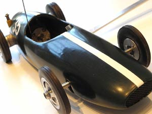
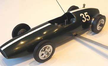
Number 35, the "simple" 2.5cc Cooper Climax car is now finished and ready for a test run on Peter Hill’s track at the earliest opportunity, so here are some pics to show the finished product.
 |
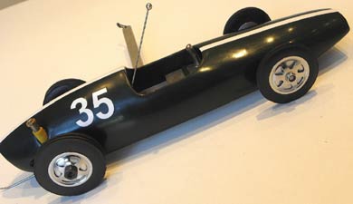 |
I finished it in dark BRG cellulose with a white stripe, though it looks almost black in the images. A handsome little fellow though, so how can you resist making something similar, to your own favourite, suitable, full size car design?
|
|
I’ve done some outline drawings for another body, close to scale for a Ferrari Tipo 500, which look really inviting to fit on the same rolling chassis and which I will probably make soon. It only takes an hour or so to find a drawing on the web, scale it to the chosen wheelbase and track and adjust the outline by hand as necessary, and then you are ready to mark out and cut wood. It would be really great to see some of your efforts come to life during the season and join this at one of the 2019 RRC track days to participate in Peter’s new class for this type of 2.5cc car. See you there, hopefully! |
©copyrightSteveBetney2019