|
Home Updates Hydros Cars Engines Contacts Links Racing ←2021 2023→ Contact On The Wire |
|
|
Oliver Monk 'Occasional Workshop Ramblings'
|
October 2022
|
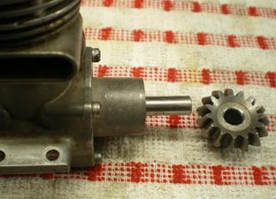
This is my latest old-timer car, an Ian Moore No.12. It has been a long time build, I would do a bit and then put it on the shelf, and this went on for a few years. Aaron painted the body for me so it was time to get it ready for the track. I have two Dooling 61’s, a beat up one that I was going use for this car, mixed some fuel 20% nitro 25% castor oil and the rest methanol. The engine started and gave a quick burst and went very tight took it apart and it looked OK ran it again same thing. So I stuck the other Dooling in it and that was OK, for its first time out it did 100 mph happy with that. I had a chat with Stuart Robinson about the tight engine he suggested it was a problem with the inlet disc set up. That was the problem. |
|
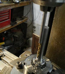
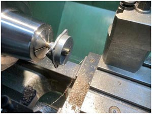
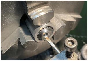
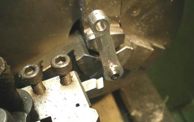
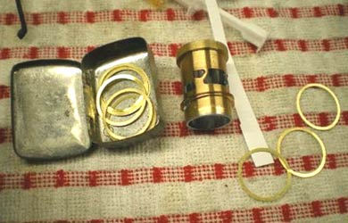
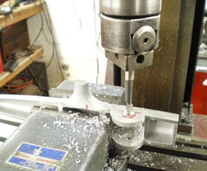
The bearing for the disc valve was badly worn, and needed replacing, first operation was to drill out the old bronze bearing. The picture in the centre is the start of a new bearing. After reaming the bearing, I check the fit of disc assembly.
 |
 |
 |
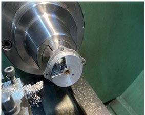
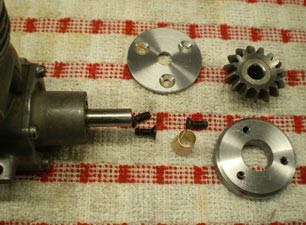
The bearing was glued to the back plate using Loctite bearing fit. Skimming the back plate up to remove the deep scores, Ready to assemble, note the shim washer, this was missing from the engine, probably caused the scoring, the metal is quite soft.
 |
 |
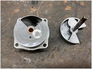 |
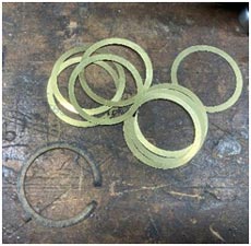
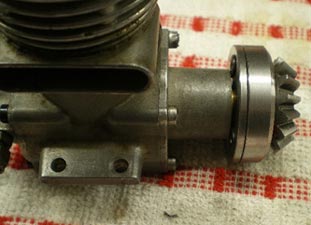
After putting the engine back together there was a distinct lack of compression, the paper gasket top left had a piece missing, new brass shims made, problem solved. The engine is now back in the car ready for a run but that will have to wait until next year.
 |
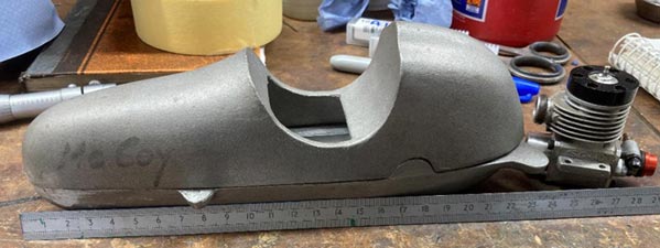 |
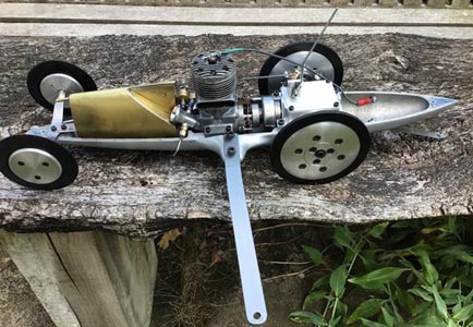
This is the next project, a McCoy mite. The casting is quite small at 230mm (8") long and the original would have had a McCoy 19 in it with a short front housing. I am going to use an Uktam 1.5cc engine running on a mini pipe to get the exhaust out of the car. The engine is not wide enough to fit the chassis, I milled out the top of the engine mounts and will bolt blocks on either side to make the engine fit.
 |
 |
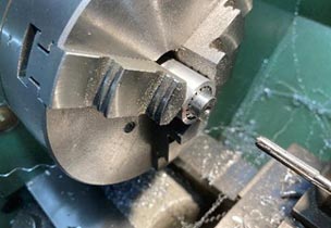 |
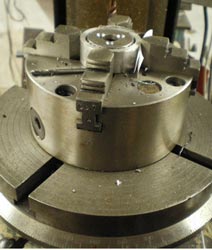
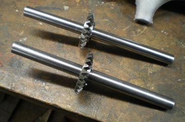
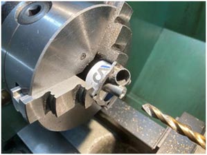
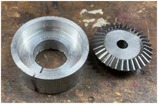
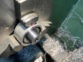
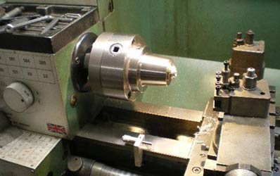
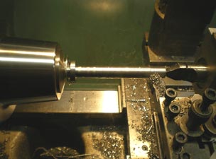
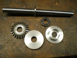
The gears are commercially available ones, but need some modification. The way I hold them is in a split cup, it works well. To get it to work consistently, mark the chuck key adjuster you have used to tighten up the chuck when fitting the aluminium bar and when you put the work back in. Bore it out to fit the gear. Before taking it out of the chuck mark one of the chuck jaws and the aluminium bar so you can put it back in the same place. You can see the marking I have put on the chuck jaw and the jig. On the right, the pinion bearing being reamed to fit the engine.
 |
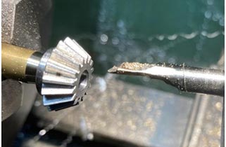 |
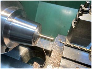
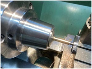
The pinion gear is held on the crankshaft by a split tapered collet. I bore the gear first and to ensure the taper is the same on the collet, I run the lathe backwards so I can turn the taper for the collet without changing anything, other than using the boring tool on the other side of the work.
That’s as far as I have got with this car, nothing else much happening in the workshop, some glider building to do on the kitchen table. Still a bit more car running to do at Buckminster before we go to Tallinn for the Lucia Race.
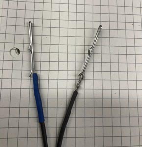
Glow Plug Connectors
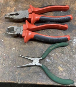
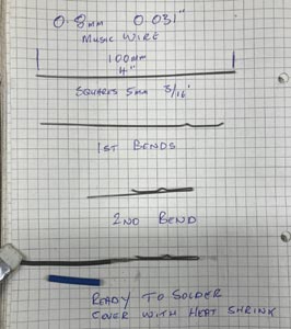
Enquiry on Facebook as to how I made hot wires "glow plug connectors" I’m sure he’s not the only one so here goes in pictures. Starting with the tools for the bending. Then pictures of the bending and the finished item. If the connecting wire is going over a hot cylinder head I put some silicone fuel tube over it.
 |
 |
 |
Workshop Ramblings October 2023
At the European Championships this year I was asked if I had been ill and unable to write the Workshop Ramblings, I replied that I was OK, had managed to avoid covid so far but was struggling to find something new to write about. So here we go, over the winter I am going to build two Ian Moore No11 cars and one for the pattern maker who is in the process of making the pattern for the chassis and of course the other one is for me.
 |
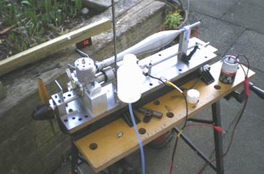 |
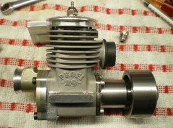
| 5cc Profi as supplied with the Picco car kits | Set up on the test rig |
This is the engine from my 5cc Class 4 tether car, it appears not to be the engine of choice for this class, the Picco and a turned round Novarossi are the ones. When I bought my Picco 5cc kit car this was the only available engine, its life did not start well, on its first gentle run on my test stand it went very tight, on investigation it was found the piston pin hole was not square. I made a new piston and the engine ran well in the test stand.
The first visit to the track in Hannover we got the car going round but the performance was not there, all sorts of advice was offered but no joy. Back at home I found the Zimmerman disc was lightly pressing onto the back of housing, when the engine was running this acted like a disk brake. Some paper gaskets between the crankcase and the Zimmerman assembly solved the problem.
Basel was the next event it ran better but the speed was still not there, Alberto suggested a little more compression that did the trick a run of 293 kph and a new British record. After the run I took the back plate off the engine, in the bottom of the engine was grey sludge, one of the tungsten counterweight in the crankshaft had come loose and had been hitting the bottom of the piston.
That was an expensive run, pistons are made from high silicon content aluminium, it had done a lot of damage. I ordered the new parts, put the engine back together. All this happened prior to covid and the car was left under the bed in its bag.
 |
 |
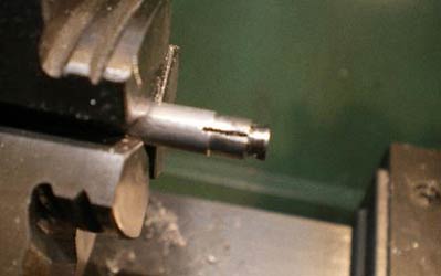
| Expanding mandrel for machining big ends | Con rod on the mandrel |
I had the opportunity to buy some Picco/Profi spare parts and on trying to determine which was which I found the conrods were slightly different size on the big end. The Profi one was about 8 thou 0.2mm thicker than the Picco ones. On measuring the Profi crankpin it was found to be shorter than the width of conrod big end, the pictures show the conrod being turned down to the correct width. No more paper gaskets and problem solved, I hope?
 |
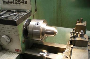 |
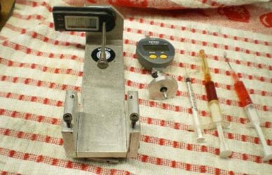
| Equipment required for setting up motors | Lathe for machining heads |
I am going to run through how I put together my tether car engines. The picture on the left shows the tools I use from left to right.
A digital timing disc
for measuring port
timing mainly the exhaust duration.
A digital dial indicator with a homemade foot on it.
A diabetic syringe for measuring head volumes.
Two syringes with one with ATF oil (automatic transmission fluid) and
the other with Castor Oil.
The other picture is my lathe very useful.
For engine cleaning I use brake cleaner, it is not recommended for bearings with plastic cages as it may damage them. For those, I use methanol.
As a first stage, check the bearings in the crankcase, check that they feel smooth with no gritty feeling as you rotate the inner, next put the crankshaft in, fit the flywheel. Then spin the flywheel, it should spin freely and when it stops rotating it should rock backwards and forwards about 4 or 5 times, if it does then all is good. In the past I have written about fitting bearings can do it again if any interest.
Having assembled the engine using ATF oil for the bearings and crankshaft and castor oil for the conrod big and little ends and the liner and piston.
The exhaust duration wants to be somewhere between 190° and 200° the actual figure depends very much on the set up of your car and the length of the tuned pipe, also how powerful your horser is to get the car onto the pipe. A good starting point is around 195°.
 |
 |
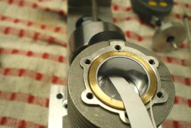
| Paper used to check the closure of exhaust port | Selection of head and liner shims |
I use a piece of paper so that I get a positive stop when the piston reaches the top of the port this method gives a small error of 1° to 2° for me this is acceptable, it gives me a consistent method of measures and I make allowance for this error.
There are other methods of doing this, shining a light through the exhaust port or just doing it visually, choose your own method but stick to one.
You can adjust the exhaust timing by putting shims under the flange at the top of the liner.
 |
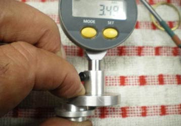 |
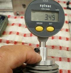
| Checking the height of the piston at TDC | Checking squish clearance |
Next is the squish clearance, this is the distance between the top of the piston measured with the piston at top dead centre (TDC) and the bottom of the head. On this engine I am using insert heads.
You will notice the gauge reads the same value, this is telling me the piston will hit the head, this is not good; on this engine I am looking for a squish clearance of between 0.3 to 0.5mm. The head will be raised by shims to get the correct value.
 |
 |
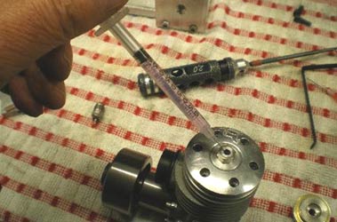
| Checking head volume | Machining combustion chamber in head button blanks |
Finally, the volume of the head with the piston at TDC as a rough guide it wants to be between 0.7 to 0.8cc for a 10cc engine so for this 5cc engine I am looking at 0.35 to 0.4cc. This volume is to the bottom of the glow plug hole. The head volume is fairly critical, too low and you will not get the performance and too high you will get pre ignition, this looks like a shot blasted finish on the head and piston and may also get glow plug failure.
I find it easier to use a dummy glow plug when measuring the volume its easier to see when the chambers full and then just deduct the volume of the dummy plug, so much easier than peering down the plug hole.
Tether car racing is supported by a variety of people making and supplying parts for tether cars and there engines usually only available at tether car events and not always on a regular basis.
The head I used came from one of these suppliers and manufactured so that it could be adjusted to achieve the volume and squish required, this is where the lathe comes in. The price of the insert heads is good as they are CNC machined and its not worth me making them from scratch.
That’s a quick run through of setting an engine up, you won't know if you’ve been successful until you run the car on the track, the challenge is working out what you need to change. Most of the people running cars will give you advice.
Next will be the start of the No11 car, if the castings are not done it will be wheels and axles or the shut off.
I can be contacted at buckytcar@btinternet.com
Workshop Ramblings November 2023
|
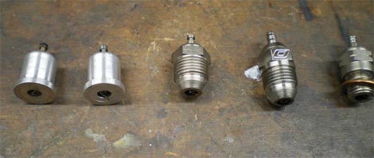
These are typical of the glowplugs used in tether cars The first two are drop-in or top hat plugs. The next two are taper seat or turbo plugs and the last one a McCoy conventional plug. These were used when I first started racing cars, the taper seat plug was just starting to be used. The McCoy type are good in the 10cc Dooling engines.
|
|
|
|
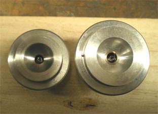
Its not the best picture but the
camera doesn’t like my LED lights above the bench, but I do, they are
much brighter. The first taper plug is a Picco and works well in 2.5/3.5cc engines but now sadly no longer available, luckily, I have a season’s worth in stock. The other is an O’Donnell plug No 260 special made for tether cars and used in the 2.5cc to 10cc engines. |
One simply rule for glowplugs, find one that works in your engine and stick to that plug. Changing the plug type and manufacturer will affect the performance of the car. Tether car glowplugs are available at the European tether car meets from a couple of sellers and at the right price. I use drop in plugs in my 1.5cc car and 2.5cc cars. Picco plugs in 2.5cc car, slightly more consistent and the 5 and 10cc cars the O’Donnell. It may seem extravagant I use a new plug every run in competition, the last thing I want is a blown plug as you only get three minutes on the cable. The good ones left over are used in practice.
This is something I started to write for publication elsewhere but it's happening here instead. It's something to think about if you are running cars at Buckminster.
How to go faster!
After the European Championships in Hannover I was talking to Torbjorn Johannessen who had just become European Champion and set a new world record. He wanted to know how I had got my car to go faster, I had made a jump of 16 kph and set a new British record. Nothing stood out as anything significant that I had changed other than a lot of little things. He agreed that was typical of getting a car to go faster.
|
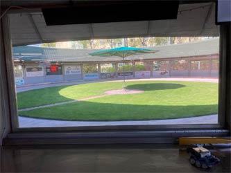
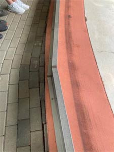
This is parc ferme at the Pila tether car track in Poland. This is probably one of the best tracks in the world, it has a coating on the running area to give good grip for the cars tyres and also has a sophisticated timing system. |
|
|
|
This is the coated part of the track, it is cleaned after all events and during major competitions. It is cleaned at lunch time and then again at the end of the day to remove the oil and rubber laid down by the cars. Tether car tracks do not seem to rubber in like F1 tracks, they seem to get slippy probably because we run two stroke engines with lots of castor oil in the fuel mix. |
|
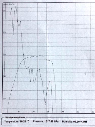
This part of the print out you get at the end of each run. This graph shows speed, the curved line with dots and the dots between the vertical lines are the timed run. The other line shows acceleration. When the line is going down the car is accelerating and going up its slowing down. In the approach to the timed run you can see the car accelerating and slowing down, this is not really shown as a change in speed as its only happening momentarily, it's wheel spin. It means you are losing some speed, every little bit helps. The two vertical black lines show my timed run, I was four laps too late pressing the button. By now you are wondering what this is all about?
|
|
|
|
|
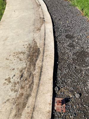
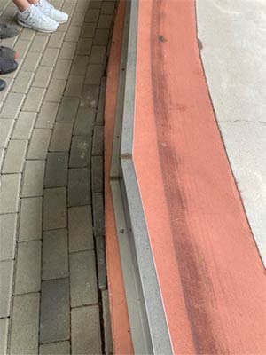
Now compare the two pictures. Apart from the track on the left being dirty, look at the width of the tyre tracks. The one on the left looks like its used by motorbikes. If we are getting wheel spin with two wheels on the track how bad is it with one driving wheel?
|
In the early days of Buckminster, before we had timing systems we were just using stop watches. I was running my Russian schools car powered by a Temp diesel engine, it sounded really fast, the engine was revving like a good one. At home I sat and worked the speed out, very disappointing. For my modern cars I have a spread sheet for calculating wheel diameter, speed and engine rpm. Using any of the two parameters, you get the third. I knew the speed and wheel diameter so the calculated engine rpm was 8,000 ish. Now, I know the Temp is not the fastest engine but it should do 14,000. It was one of two things, wheel spin or bouncing.
More to come next time.
Also the start of the Ian Moore No 11 car.
If you want to contact me buckytcar@btinternet.com
Workshop Ramblings December 2023

Back into the workshop after a break in the sunshine and the cold in Poland, -11 C and about 8" of snow, but missed the Lucia race this year.
|
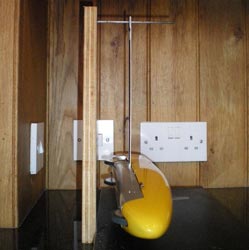
Setting up a car: Returning to going faster. You need both wheels in contact with the track to help avoid wheel spin. This is my 1.5cc car hanging from the cable attachment. You can see that the car is hanging so both wheels will be in contact with the track. This is the first step before you run the car, measure and record the diameter of the driven wheels. After a few runs you should have a measurable amount of wear on the tyres. This should be the same for both wheels, if not either bend the tether up if the wear is on the outside wheel or down for the inside wheel. Repeat until you get even wear. |
|
|
|
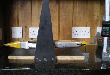
This picture shows the checking of the balance of the car, always done with a full tank of fuel. I measure the front and back of the and record the difference. You want the front/nose of the car pointing out of the circle. When the car is running the cable will have a bow in it which will pull the front of the car in a little (control line pilots will know this). The balance of the car also affects the fuel supply to the engine. As the fuel is used the front of the car begins to point into the centre of the track making the engine go leaner. If the car is pointing too far out it will scrub the front wheels and the engine will tend to go rich as it accelerates up to speed. No magic number for how much the car needs to hang out to work, it is a case of trial and error. A starting point is 5 to 10mm depending on the length of the car |
|
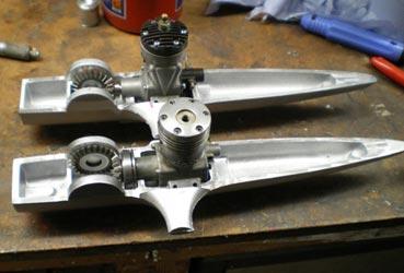
The two
Ian Moore #11 5cc cars being built in parallel The castings as they came from the foundry and the engines to power them. Mine's the ETA 29 the other a Dooling 29. (Original castings will have either a single mounting foot as seen here to clamp in a machine vice, or up to six feet to bolt the casting to a plate for machining. 2nd or 3rd generation castings will have neither, making holding them exceedingly difficult) |
|
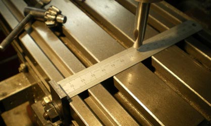
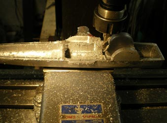
The first picture is setting up the centre line of the milling machine table on the digital readout and the second setting up the casting on the centre line ready for milling the cast-in mounting foot.
 |
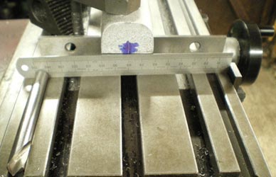 |
With the casting set up on the centre line, the spigot on the bottom is machined up so that casting can be put into a machine vice on centre and with the top parallel, it makes it much easier to work on the chassis.
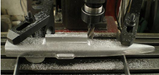
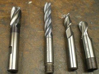
Below are the cutters I used in machining the chassis. The first two are ripping cutters, good for quick easy removal of metal. The next is an end mill for aluminium, these are sharp, and finally a ball nose end mill, sharp corner are not good in some cases.
 |
 |
The engines and the gears in. On to the next stage, fitting the rear axle.
 |
 |
 |
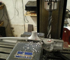
The advantage of having a lug on the back of the chassis casting and machining it as described earlier is that it's easy to set up. The chassis lug is on parallels to keep it level with the milling table and the vice keeps it square. Make sure the axle centre is the same as the engine crankshaft centre to get the gears to run smoothly. Drill first and then bore to size. My boring head was rescued from the scrap man when the factory tool room was moved. Its proved to be very accurate, put a one thou cut on and that is what you get, maker unknown.
Wanted anyone have a Jones and Shipman 4" machine vice like the one in the picture for my son Aaron? He’s happy to pay, drop me an email if you have one.
 |
 |
 |
Left: The axle being machined. It is important you use a centre to ensure the axle stays parallel. In the absence of a collet chuck a four-jaw independent chuck can be used to keep both sides concentric. In the centre picture are the bearing carriers that support the rear axle, a straight forward turning job. The bearing in the picture was used for getting the fit right in the carriers, the ones fitted to car on final assembly will have shields to help keep the muck out.
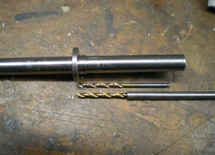
Drilling the flange for the gear can be a bit of a challenge but there is an easy solution with extended drills. Tapping the holes was done the same way with an extended tap. The drill and tap were stuck in with Loctite retainer, and to get them out some heat does the trick.
|
|
|
|
| Drilling and countersinking the holes | The gears fitted to the axles | |
I have had a couple of questions.
I use a hollow glowplug when I am measuring the head volume in an engine it’s just so I can see that the head is full. The volume of the hollow plug is 0.09cc this is deducted from the amount of fluid I have put into the head and gives me the actual volume to the bottom of the plug hole/top of the chamber.
The question is how to fix the flywheel on the Dooling 29 engine in the No 11 car.
 |
 |
 |
The pinion gear has a taper in it, I have use Loctite retainer to hold the gear in the flywheel. If this doesn’t work, I will put in some grub screws. The flywheel has 3 tapped holes in it with a matching backplate.
The assembly is as follows the backplate goes on first then the brass split collet, followed by the flywheel, fit the three countersunk screws and tighten evenly. And that’s it. The work continues on these cars into 2024
|
Finally, Aaron and I needed some new "T" shirts for when we compete abroad. We worked with a local artist to come up with the design. These are the samples I have had done by a local print shop. Last time I did this I caught a financial cold, not sure how I am going to do it this time. The print shop will do small quantities and sweat shirts etc as well, the prices seem reasonable. Also having some stickers done as well, should be ready by the new year. My contact email buckytcar@btinternet.com
|
|
©copyrightOliverMonk2023