|
Home Updates Hydros Cars Engines Contacts Links Contact On The Wire |
‘Triton’, an intriguing tale.
|
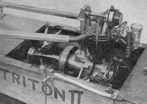
"The 1950 Model Engineer Exhibition had little of real interest in I/C engines", so goes the report by Edgar Westbury. "But a notable exception was the 15cc overhead-camshaft engine in the one example of a racing hydroplane by G. D. Reynolds". The boat was Triton II, and such was the level of craftsmanship, that it was awarded a bronze medal in the exhibition. In a series of detailed articles in ME, Doug Reynolds had described the building of the engine and the original boat, that gave a fascinating insight into the work of this consummate engineer. Recently it transpired that not only did Mr Reynolds write the articles for ME but also he kept meticulous notes, drawings and photographs of the development of the boat and engine, as well as retaining all the discarded parts as development had progressed. |
|
Following a very kind invitation to view all this material, Mr Reynolds’ son John has given OTW a unique opportunity to publish Doug Reynolds’ account of building and developing this amazing little engine and the boats it powered.
|
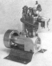
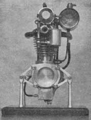
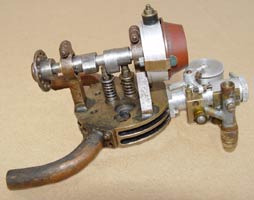
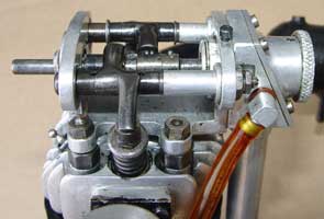
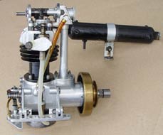
"In the winter of 1948 I looked around for something to do in my workshop-the spare room. By chance I had met Mr Dray of Farnborough, and after having a very interesting evening at his workshop, I decided to build a 10cc overhead camshaft engine similar in many ways to his engine". Pictured right: Mr D.H. Dray's 10cc OHC four stroke engine that was described in the Model Engineer in March 1949. The similarities between this and Doug Reynolds' engine can clearly be seen in the photo above. Both engines feature crankshafts inserted from the rear of the single piece crankcase which makes for an interesting engineering challenge with a four-stroke engine. |
|
"I drew up plans of the type of engine I had in mind and decided that the crankcase would be the first job. This was made from solid duralumin, all the profile milling carried out in my 3-in. centre lathe. My idea in making the crankcase so complicated was to find out just what type of milling I could carry out with the little equipment I have. This proved very satisfactory and was completed in approximately three weeks of spare time.
I next made the cylinder of duralumin with a tool steel liner hardened and tempered. The cylinder head was made from bronze with twin exhaust ports: the camshaft brackets are brazed in and bored to take ball races".
He goes on to describe making the camshaft and adjustable cams along with the bevel gear drive to the overhead camshaft and the extensive effort to get this all working smoothly.
" The crankshaft was made from solid nickel chrome-steel and the connecting rod of duralumin, bronze bushed at the small and big ends. The piston was made from a piece of cast aluminium bar with two cast iron rings".
After discussing the making of the valves, guides and valve gear came a problem!
"It was at this stage that I realised that pressure lubrication was an essential part of an engine of this type. I seemed to have slipped in my first plan---so I decide to fit a gear pump to the camshaft"
A detailed description of the oil pump, non-return valves, sight glass and sump just left the fuel system to complete.
|
|
"An Atom type R carburettor was fitted. I only had a plan of a 30cc type and no castings so I decided to prefabricate them, the body from dural and the tubes from brass. The float chamber is fitted with a metal float made from .003 in. brass, spun in the lathe. After giving the engine a good run in for approximately four hours on my lathe, it was completely dismantled, cleaned and then reassembled. I had it firing in about ten mins. After a little alteration to the valve overlap, I clocked 1,500rpm slow running and 9,300 rpm fast running, thus surpassing anything I had expected to get from an engine of this type. The building of the engine has afforded me eight months of complete enjoyment known only to we model engineers". |
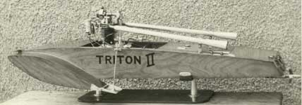
The engine was described in detail in ME for Aug 18th 1949. It was his intention to fit the engine in a hydroplane and construction was started in August 49 two months after finishing the engine. The hull was completed during Dec 49 and Triton II, with the engine fitted, appeared on display at the ME exhibition of 1950, but over the course of the previous year the engine had undergone radical development. Triton was a conventional three-point boat built with ¼ square spruce stringers on 1/8th ply formers and skinned with 3/64th ply on the bottom and 1mm on the sides and deck. Casein glue was used throughout. The description of the boat can be found in ME for Aug 24th 1950
|
|
|
"Oil pump was on camshaft but owing to oil failing to lift from sump decide to move below sump after trying non-return valve in sump. New oil pump housing made & fitted. Oil pump driven from propeller shaft by worm gear 8:1 first used Meccano gear but reduction ratio was 16-1 made new 2 start worm gear.
Petrol tank was gravity fed to float chamber decided to fit petrol tank into boat. Diaphragm petrol pump made and constant level fuel chamber for carburetter. Exhaust pipes too short larger pipes fitted giving better extraction at 7000 rpm.
Boat tested, very poor performance- not enough blade area, too much pitch on propeller. Run big end while testing engine; make new big end & cast iron piston in place of aluminium one. Altered crank case breather- took pipe to camshaft gears. Valve timing bad- decided only remedy was new cams".
There follows four pages of detailed diagrams and description of cam design, timing and manufacture, a page of new props and a jig for brazing on blades, details of three new pistons and experiments on the carburetter choke. On 30th Jan 1950 all the relevant settings for the cams, valves, ignition and carb settings were set down and it was noted that the fuel being used was Ronson lighter fuel.
31st Feb 1950. Fitted megaphones to exhaust pipes to give better extraction
23rd May. Engine testing. Boat will run well on Eveready battery No 800- skeg bearings far from satisfactory-considerable forward thrust required to get the boat away- crankcase main bearing cup working lose.
|
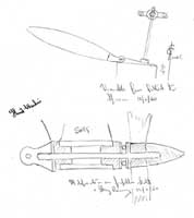
Modifications carried out week ending June 2nd 1950 Decided exhaust ports and inlet ports were not large enough remade cylinder head & proceeded to open up ports. Cut the fins on cylinder head deeper all round to try and get better cooling. Fitted new valve guides. Reduced weight of flywheel to 10 ozs-engine assy 3lb 4ozs less flywheel. Modification propellor shaft & skeg bearings 12/6/50. Only one thrust bearing required. 2" variable fins fitted to sponsons. .....................Right: Doug's sketches showing new skeg and variable planes. |
|
Setting 22nd June 1950- 50% petrol benzole mixture.
5th July 1950. After tests on engine 22nd June 1950 I decided the engine was not powerful enough for the hull. On checking I find that by making a new cylinder from the solid this time I could just measure the bore to 1.07" which with a 1.000 stroke would limit this engine to a 15cc. (note: - at this stage a quick crunching of numbers shows that with a bore and stroke originally set at 7/8th in. the engine was just 8.6cc .)
New cylinder made from centrifugally spun cast iron. Piston. Alloy made from old car pistons melted down.
This then was the stage of development that Triton II and the engine, now 15cc, was in when displayed at the ME Exhibition in 1950.
Week ending 6th Nov 1950. Decided that after numerous tests the ignition system was far from satisfactory-decided to purchase MI ED magneto this was fitted to the propeller shaft with 1:1 skew gears.
Nov 1950. It appeared obvious after fitting engine out for 15cc that the old cylinder head was no good-decided to make one from Duralumin with semi-spherical head and bronze valve seats. Contact breaker had to be fitted to rear of engine to allow sparking plug to be fitted to front of head. New gear box cover made to carry contact breaker assy.
|
|
|
|
|
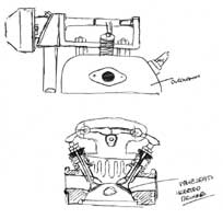
Original bronze cylinder head. |
Design sketch for new cylinder head |
New Dural cylinder head with glow plug fitted. |
Jan, Feb 1951. After watching models at Victoria Lake at the MPBA regatta 1950 I was very impressed with the fine taking away of boats fitted with automatic throttle control. Mr Mitchels BETA & GAMMA also Williams FARO. Decided to work with a train of gears from an old clock. I then took the path of least resistance and used an hydraulic damper. The damper gives 5-8 seconds delayed action.
18th April 1951. fitted a crown to piston to higher compression. Compression ratio 11:1 fuel 50%/50% petrol benzole. Fitted high compression piston 12:1. After several runs decided compression too high. Running on methanol.
28th April 1950. Completely dismantled engine, checked for wear. Big end getting worn decided to fit new large and small end made bushes of nickel bronze. Piston dome lessened to reduce compression to about 10:1. Front and aft deck panel to be repaired through damage on test runs.
15th May 1951. Have carried out various settings and ignition timings to try and stop surging at high speeds.
4th June 1951 Decided to try a glow plug- made 3/8 x ¼ adapter to take champion Glow plug USA. Tried out engine using straight methanol. Remarkable performance
|
|
|
|
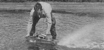
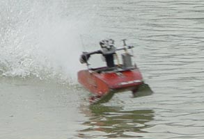
Triton 2 having a test run at Fleet Pond in 1951. |
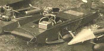
and in modified form with Jim Bamford's JAB 1 and JAB 3 in 1952 |
Tuesday 19th June 1951. Modification to outer planes-removed sponsons fitting dural sponsons to Triton
Jun 22nd 1951 Checked weight of engine and hull. Engine complete 3lb 13ozs
Hull propeller shaft 4lb 14ozs
Total 8lb 11ozs
Aug 12th Fitted new forward rocker shaft bush.
At this stage entries stop for a year as a new project was under progress, a 30cc rear rotary valve two-stroke engine and boat Triton 3. Comments about ‘Triton II’ are now limited.
Aug 6th 1952. Fitted rear skid to aft end of boat-reset valves.
Aug 7th 1952. Fitted stronger valve springs- fitted new bearings in skeg.
24th aug 1952. Fitted cut off valve for fuel after fitting new carburettor. Big end of conrod split, have to dismantle engine.
25th aug 1952. Made new con rod, enlarged dimensions all round.
During the winter of 52/53 a completely new hull was built for the 15cc engine. ‘Triton 4’ from obeche and balsa was much lighter at 7lb 4ozs all up. The new boat was tested on 3rd April 53
Fuel Methanol. Nitro Methane 90% 10% Oil Castrol XL
First run 43 mph. Second 45 mph. Third 45 mph. Fitted 1/8th in transom plate to stiffen skeg. Overhaul upper half of engine, fit lighter valve springs.
Triton 4 run 19th April 1953. Very bad running only aprox 40 mph. Trouble with carburetter, valve springs etc. Fitted stronger springs re set valve timing. Shortened exhaust checked pump.
At this stage problems with the stability of the boat are noted and a series of experiments made with differing tether points to cure the problem.
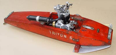
Nothing more is mentioned about this boat and the next entry is for a new hull, again from balsa and Obeche. ‘Triton 5’
|
1956. New hull-engine fitted with new main bearings new big end. Valve timing adjusted- fuel now 65% methanol 15% nitro methane 20% castor oil. New choke tube- new tank. First run 46 mph second run 48.5 mph. New prop made. First run 50.1 mph second run 51 mph. 60 mph recorded on two laps. 5-7-57 Triton 5. Fuel tank fixed-new setting device to ensure max use of c/f. Extra rich jet fitted to carburetter. There are no more entries relating to the engine or boats but at some stage, Triton 5, which was built with outrigger sponsons on dowel bars, had the sponsons cut off and a pair of aluminium planing strips screwed to the bottom of the hull. |
|
With the exception of the fuel system, Triton 5 has survived in this state and whilst only the crankcase and flywheel of the original 1949 engine were incorporated into the later motor, there exists this wonderful record, both in words and components, of the hard work and continued development that were involved with this engine and the hulls it powered.
|
|
|
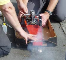
Post Script:- Following the discovery of Doug Reynolds' photo album and original prints of Triton 5, a member of the Retro Club undertook to reconstruct the fuel system with a view to running the engine again. With two photos for guidance a new tank, mounts and air bleed needle were built and fitted, and the boat taken to Victoria to see if the the system was anywhere close. With a tank full of 10% nitro fuel, a few tugs on the starting cord gave encouragement and tweaks to the two needle valves soon had the engine running happily for the first time since 1991. A quick decision was made to fit wire bridle lines for the next weekend to fulfil a promise by attempting to run the boat on the water using a modern line.
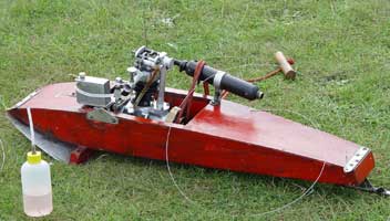
At first, Althorne Lake was uncooperative, being far too rough, but after lunch it calmed down enough to make an attempt. With the heavy A3 cable attached, the engine started readily and a successful launch saw it off on its first run for over 30 years. The slow revving engine and large prop shifted plenty of water and the boat kept tension on the cable as it ran merrily round the circle. Finally the fuel ran out and the boat came to rest, a fitting end to this intriguing story.
|
|
|
|
|
Running on the new fuel system. |
Significant 'overkill' with the strength of the bridles. |
First run for 30+ years. October 07 |
A second article takes a more general view of the life and other engineering activities of Doug Reynolds.
OTW is extremely grateful to John Reynolds for all the items, material and photographs that have made this and the subsequent articles possible.
©copyrightOTW2007