|
Home Updates Hydros Cars Engines Contacts Links Contact On The Wire |
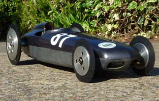
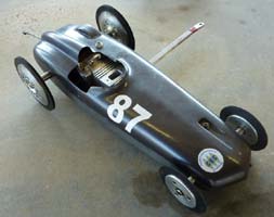
A 'real rarity'. Mark Mansell builds a 10cc racing motor.
Why bother spending untold hours of drawing board and workshop time building a motor, rather than handing a wad of notes over the model shop counter for a tried and tested commercial engine? Well, at one stage that was not even a choice, but for many years the nice shiny box has been the route most have taken. Even to the extent that, for a very-very large wad of notes you can have in your hand a 10cc car and motor, guaranteed for over 330kmh. Fast enough to bring home the silverware on a good day, but with the strict proviso, that other than fuelling, oiling and pushing off, the car is not touched? There are still those amongst us, that prefer to do it the hard way though, and all power to them. It can be effective (if you are Swedish) but more often it is very hard work and frustrating, but what a sense of achievement when that homebuilt motor runs for the first time. More so if the car, boat or bike completes a race or run, and if it ends up competitive, well, what is that worth on the feel good factor scale?
In this lengthy and detailed article, Mark Mansell shows us something of what goes into the building and developing a racing engine from scratch. OTW takes its hat off to Mark for this venture.
|
|
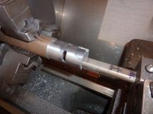
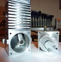
The earlier pictures of the cylinder liners are from this engine. Which is in the Indianapolis Watson roadster type car with the one piece back axle. (Drive gear is machined integral with the axle so it starts as a very large piece of metal) Front axle is one piece too but nowhere near as exhausting to make. These pictures were when it (the motor) had the original hard chromed brass liner and aluminium piston. Well before the brass piston ring was fitted. Waste of time that was anyway. |
The liner and piston are probably the most vital parts of the motor in terms of design, engineering and metallurgy. Port numbers, position, size and shaping control ultimate power output and the materials and fits determine just how long the piston continues to go up and down at the normal 500 or so times a second.
 |
 |
 |
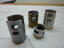 |
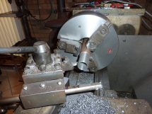
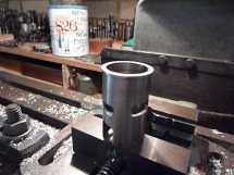
| Cylinder liner from scratch 10cc engine in the lathe caste iron bar being roughed out | Outside diameter and bore being left oversize and under size intentionally | After milling the ports it goes back in the lathe for finish turning thus negating the annoying job of deburring the ports | I forgot there was another one in mild steel but it didn't work with the aluminium either |
 |
 |
 |
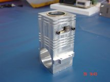 |
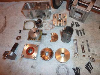
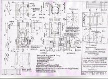
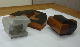
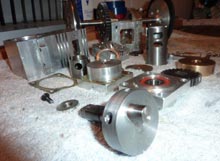
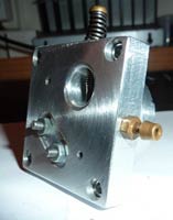
| All starts with drawings | Shell patterns | Conventional split patterns and core boxes | Crankcase centre section |
 |
 |
 |
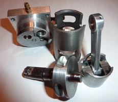
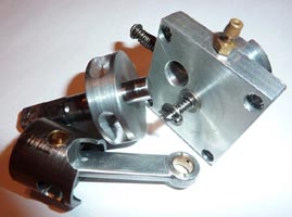
 |
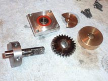
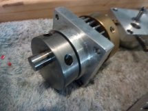
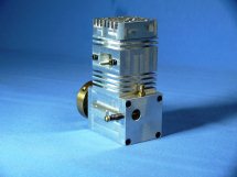
| Very short crankshaft | Crank and front housing | Assembled motor looks a treat | |
So, to the track. Well it started OK and by the time I had ensconced myself in the timing cage I was seeing 85 on the speed digital readout. This slowly increasing to 107 and accelerating well when it just stopped. I reluctantly pulled it down in the pit area. I prefer to do this in the sanctity, secrecy and luxury of my home workshop. However I had to know where the tightness was coming from. Bronze deposits left on the crankpin were a giveaway that something was very much up the spout. I think the English might have described it once as "much binding in the marsh". Well what ever sort of binding it was I had found it.
|
|
Where would one find some wet or dry 1200 around here? I asked myself. Having spent years in engineering there could be a sure place. In the lathe chip tray of course, there is always a bit of emery paper there. AND there WAS. So judicious handwork with the crank held in my right hand and the wet or dry in my left and wrapped around the crankpin, I started polishing procedures. After reassembly It seemed free again. So back on the track it went. After only 2 pushes it was even tighter than before. OK..............now to the home workshop. This needs serious surgery. Reluctant pull down at Luddenham, bronze deposits on
crankpin. |
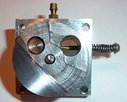
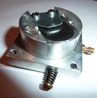
It seems that the entire crankshaft assembly has migrated towards the disc valve and turning the disc valve into a disc brake, effectively. I was never entirely happy about running a bronze disc directly on the aluminium crankcase. But it was the only material I had and tempered with the thought that it would be running on fresh fuel and oil on every upstroke, my reasoning was it would be OK. Looking for a bit of steel or carbon now. But why has the crank moved?
Yes the crankshaft has moved in its bearings. This forcing the disc valve against the disc cover and the crankpin (being hardened steel) wearing bronze off the drive hole in the disc. This bronze finding its way into the big end bearing and welding itself to the crankpin. Pass me the Loctite please!!! Might have to machine a couple of small pins to locate the bearing outer races. Just looking for the drawing now as I find it hard to believe I didn't locate the main bearings. Unless the crank case has cracked around the outer bearing ring. Oh NO.
Problem located and rectified. OK you can call me a butcher, I confess. The outer race has now been "staked" with centre punches X8 around its outer housing periphery. But before I re-assemble the engine I want to lighten the piston a little by drilling 4 blind holes 0.125" dia. adjacent to the gudgeon pin holes.
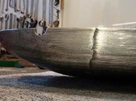
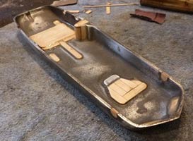
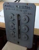
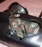
Development of the engine was not helped by a piece of rubber coming out of one of the rear tyres at 142kmh. The ensuing vibration is almost beyond belief and before the car could be shut down had caused stress cracking around the hold-down screws for the bodywork. (see photo below)
 |
 |
 |
 |
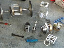
| See note below | All the parts required | Vibration caused by a chunk coming out of the tyre did nothing for the bodywork | |
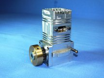
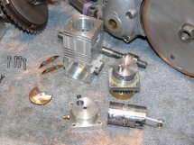
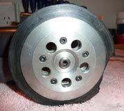
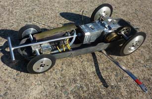
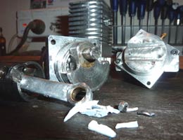
You can just see the drive gear peeking out behind the brass flywheel. Engine in the background is the 1948 James Comet 98cc Villiers two stroke. The bike is getting very close to be put on club plates now.
 |
 |
 |
Stay tuned for more on the mysteries of two-stroke tuning from down under. Mark Mansell
Winding up very nicely at about 148 and the roar from the engine was wiped out by complete silence and then as our ears adjusted to the deafening quietness, a swooshing sound as it was hurtling around the pole with the engine locked up solid and then the overwhelming smell of burning rubber as the back tyres were ground into a fat ‘D’ shape. Being satisfied with the fastest run the car has ever done, I was at first a bit philosophical about the whole thing. When I took the body off and analysed the extent of the damage, I was heard at the other end of the pit area in a lamentful scream crying, ‘OH NO, I can’t believe this!!’
The flywheel had worked its way loose and in doing so had pushed its retaining screw up against the magnesium chassis pan, thus forcing the crankshaft over against the disc valve (again) and pushing the crankpin through the crank web. The disc valve is totally stuffed as is the 2 x grubs and retaining screw for the flywheel. The thread, M4, was totally stripped and the body work torn to shreds by the flying grubs.
Its nearly all back together again. I have re-drilled and tapped the crank shaft to M5 x 0.8 and made a new screw. Made a new disc valve out of steel this time and it has turned out really nice off the surface grinder. I left the crank pin in its new location and ground the protruding bit away to clear the main bearings. Finished a new set of gaskets this evening and after I find 2 new M4 grubs for the flywheel it should be ready for the track again, after I fix the body work. Which I must confess is looking rather shabby now after such a hard run.
Whilst the engine was apart I took the time to lighten the crankshaft on the crankpin side and also lighten the rather heavy cast iron piston by drilling bigger holes adjacent to the gudgeon pin bosses and opening up the boost port window to align better with the port. I also took the exhaust port up by about 5 degrees either side of BDC. Exhaust port timing now is in the order of 180 where it should have been all the time. And one head gasket shim is removed.
So now we wait until it runs again.
Well its slowly going back together. I’ve actually taken advantage of the situation to lighten the piston and remove a bit of metal from the crankpin side of the crankshaft. This should bring the balance factor back a little closer to 68%. But I would much prefer 55%.
 |
 |
 |
|
I also took the exhaust port up by about 5 degrees. Ex timing now very close to 180. Blowdown is 26 degrees and boost port and both transfers at the same height. |
Squared off boost port hole in piston. Long rod to stroke ratio gives lower piston accelerations at equivalent RPM than more conventional engine designs. Brass buttons clearly seen to locate gudgeon pin. |
Lightening of the non sealing side of the new disc valve was going along quite nicely until the damn thing moved on the magnetic table under the grinding wheel and put that great gouge in near the crankpin drive hole. |
The new rotary valve is better than the old one which was so badly bent after the crankpin went through it that reclamation after the blow up was not even an option. The new one is high manganese steel and should bed in a lot better than the old bronze one. Being steel it was able to be surface ground and thus should seal a lot better than a parted off bronze version. Pictures show lightening of the crankshaft and bigger holes adjacent to the gudgeon pin bosses in the piston. Also the window for the boost port has been squared off and a bit of weight taken out of the piston. Same old cast iron liner. Good stuff is cast iron. Highly underestimated material. Very fiddly work though. Bore and stroke are 26.16mm x 18.26mm respectively giving 9.82cc. I am more accustomed to working on 500cc single cylinder 4 strokes.
|
|
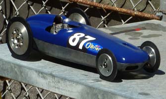
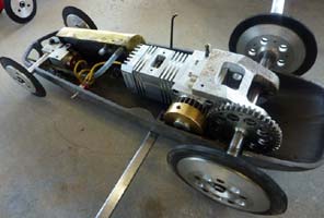
Car resplendent in its new colour scheme in the January sunshine at Luddenham. Ran at 151.88 and did not blow up!! |
Update Mar 2011. Perhaps the motor stayed in one piece, but it was not quite all good news.
So I made the new disc valve axle and was re-assembling the car when I noticed a crack in the magnesium chassis casting.
|
Cracked chassis. So started filling holes and machined surfaces to convert this into a new foundry pattern. A bit of reinforcing never went astray. |
|
|
Update Feb 2012 Car and modified motor back together, so out for the first run of the year, and not good news. After the last disaster my son suggested converting the engine from disc rotary to reed valve induction.
The first reed was made from an old credit card. It’s retaining screw worked loose and proceeded to destroy an otherwise good engine. The head of the loose and unwinding screw got hit by the crank pin and decapitated. OK my fault, I underestimated the success that the reed valve might achieve and as it was really starting to get going. I suppose ‘greed for speed’ took over and I was watching the digital read out going up and up and up.....................until it blew. The engine seems to have less friction without the constant drag of the disc ‘brake’.
Now looking at ways to prevent the screw holding the reed from coming loose and getting clouted by the crankpin and causing a big mess. For its first run as a reed valve engine it was very promising. Now to hone in and get serious.
Anyhow everyone seemed really sad for me but I was elated at the potential. Well........until I started to pull it down. The damage was catastrophic to say the least. So over the last couple of days I have been slowly rebuilding, crankshaft (again), connecting rod, cylinder liner, main bearing carrier (again), piston, cylinder head and mostly making a new reed valve and housing. The new reed is spring steel 0.006" thick. Still at the same angle so the crank pin clears the screws (note plural), which are now fully threaded through the casing and lock-nutted on the outside. Such happiness. Can’t wait to try it again.
 |
 |
 |
 |
| Mechanical carnage! |
Witness marks from the earlier blow up are quite evident. |
Lock nuts on the outside with provision for the screws to be drilled for lock-wiring at final assembly. |
New crank shaft with damage to the big end area of the connecting rod and inside of crankcase still visible. |
©copyright2011MarkMansell.