|
Home Updates Hydros Cars Engines Contacts Links ←Previous Contact On The Wire |
|
|
John Goodall Building and racing retro tethered cars |
M&E Wasp rebuild
A few years ago I obtained an almost complete M&E Wasp tether car missing just the front drive wheel discs and hub and off a very good friend, the body parts for another car. Strangely the tyre and fixing screws were with the car? I decided to try and help an enthusiast in USA who was advertising for a Wasp through the excellent and free OTW advertising service. He seemed very keen on my offer to let him have the almost complete car provided I found the missing wheel discs and hub. I did not expect to find the correct wheels discs in useable condition having searched for some previously for the car. The hub is a simple turning operation on the lathe, but the wheel discs entailed making a suitable press tool to produce the discs in exactly the same manner as the originals, so that they matched.
One of my first jobs after a five year engineering apprenticeship was as a "Jig and Tool " designer, so this came fairly easily to me. The only difficulty was in getting the correct pinch on the tyre by adjusting the hub width, once the size was determined; it was very easy to replicate the hubs for the other wheels. A simple drill jig was used for drilling the hubs and the wheel discs, so they line up well using the bore for location. The drive wheel hub only is fixed to its shaft with, in my case, a socket head 6BA grub screw, this is neater and a better solution than the original bent L shape idea? The bent end may or may not be in the correct place to fit between the discs and if not, what happens?
 |
 |
 |
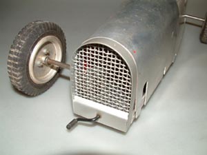
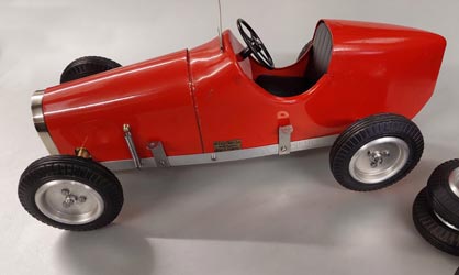
| Starting point |
Original painted grill and starting handle. |
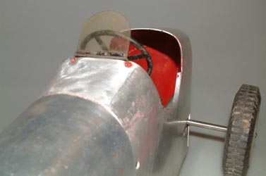
Original windscreen and steering wheel. |
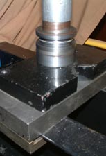
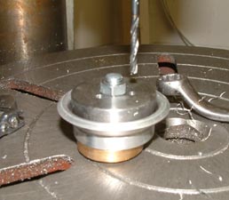
I made a punch and die in mild steel, which I deemed adequate without hardening for the fairly small numbers needed. When making a punch and die combination, the die usually forms the outer dimensions and the punch the inner with the clearance between them governed by the material thickness plus a small clearance tolerance so that binding does not occur and it is also easy to remove the part from the tooling. An essential feature of any tool design is some form of location so that the material blank sits centrally within the tool. I decided to use the central hole in the wheel disc which also keeps it central on the hub assembly and to use this location in all the ensuing operations, so the appropriate size hole was drilled into the blank alloy sheet after marking out the blank size required with a calliper.
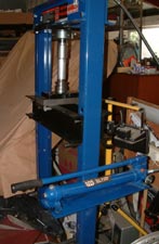
It is always best to check the press tool result on the first example to see if it is the correct size and form after pressing, as it might need adjustment. The disc blanks were then cut out using hand shears as accurately as possible. The discs were pressed up using a hydraulic press I have for basic garage work on my vintage motorcycle repairs. Adjustment in clearances and corner radii is sometimes needed after the first two or three pressings and when satisfied I made up two complete sets plus the spare pair needed for the car to be sold to USA. The outer diameters were trimmed afterwards using the press tool punch as the fixture to ensure true running and with a pressure pad to hold it onto the punch using the tailstock. A form tool was then ground up and the excess material on all the discs trimmed off and deburred.
 |
 |
 |
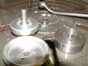 |
| Hydraulic Press | Press tool | Jig Drilling discs | One down seven to go |
I needed a clutch, gearbox, dummy steering wheel, dummy radiator grill, dummy seat, tether arms and all the running gear for the second car which I set about making before I parted with the now complete car so I had a reference to all of the parts that would be needed. I made drawings for wheels, hubs, the clutch and gearbox before starting on the chassis.
 |
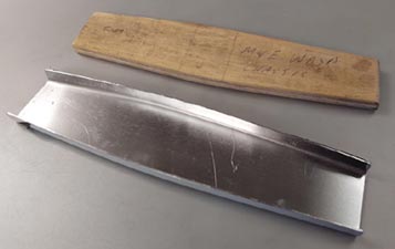 |
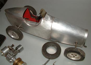
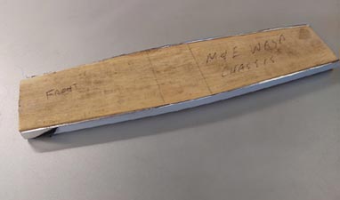
I made a plywood buck to manufacture the chassis pan in aluminium as one of the first operations in the new build. I used a wooden block to assist in folding the edges over to avoid excessive hammer marks often made without one. It saves a lot of work later in cleaning up and maybe prevents weakening the sides as well when these marks are filed up to remove them??
|
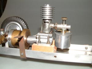
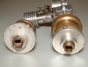
I had asked a few likely contacts if they might have a spare clutch and one thought he might have two and that one might be spare. I eventually obtained this, but did not see initially, in the hub-bub of a swap-meeting, that it had been badly modified before parting with a new original Dooling 61 crank shaft and connecting rod in part exchange and was also generously given £10 cash?? The clutch had also been modified to suit a smaller engine than for the intended and the more usually fitted ED 2cc Penny Slot. I had chosen this ED as it did not need an unsightly cut out in the bonnet (or hood?) for a compression screw. The main housing had been shortened, reduced in diameter and its bore had also been over drilled and I ended up only being able to use the clutch drive hub and the three clutch shoes, the rest had to be re-made to the correct style and size, turning the parts on the lathe. A much more costly operation in the end than envisaged. Right: ED 'Penny Slot'. The wooden mounting blocks are correct |
|
|
|
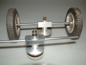
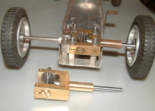
I had not found a gearbox for the second car so decided one had to be made and Hugh Blowers kindly found me a set of suitable 1066 bevel gears of the correct ratio to make the gearbox. I obtained some ½" x 1 ½" x 3 ½" long brass bar, marked it out and roughly cutaway most of the excess on the band saw. The final dimensions were machined on my Bridgeport milling machine with the output wheel bearing and its bore machined using a four-jaw chuck in the centre lathe. The input bearing and all fixings were drilled and bored on the Bridgeport using the DRO indexing and the gear centres came out almost spot on, just needing a four thou shim behind the drive pinion to obtain the correct backlash, just perceptible without tight spots. Bright mild steel was used for the two shafts with the gears pinned to them. Left: Replica steerable rear axle with original behind |
The final drive gear can only be fitted after the input gear is mounted on its shaft and an adjustable screwed end bush bearing fitted to remove end float. This is gripped solid when the gearbox is tightened down onto the chassis with a saw cut machined to clamp the bush and prevent movement.
 |
 |
 |
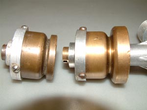
| Original M&E Clutch with the much modified one from the 'trade' | New gearbox looks superb | |
Next came a dummy radiator grill made mostly out of brass sheet with the rounded top surround made in two pieces with a lower joining piece between folded to suit and the whole silver soldered together with high temp silver solder. This allowed silver soldering the wire mesh with a low temperature solder without melting the main body joints.
|
|
In hindsight maybe stainless steel mesh should have been avoided for ease of nickel-plating, but it can be achieved with a special process. It may have been easier with brass mesh although much softer. I made the side cheeks with two mounting holes each side to prevent the back and forth movement seen with just the single screw each side. I added a brass bearing for the dummy starting handle silver soldered into the cross member. This kept the spring friction device clear of the mesh for a better solution to the original. The starting handle was bent up from mild steel and a 6BA screw thread, with nut added to retain the spring. A dummy steering wheel was made up from brass sheet for the four support arms in the form of a cross. A central pivot and column was turned up in my small lathe in two parts and a ring for outer rim bent up in brass wire, the whole being silver soldered. Not perfect, but just adequate. The starting handle and steering wheel were etch primed and painted black. |
|
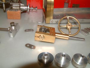
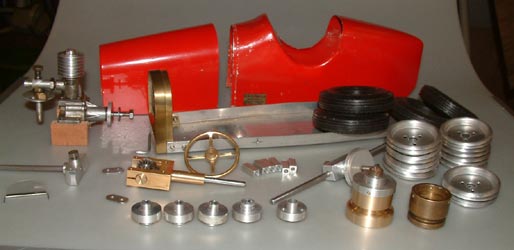
At this stage I drilled the fixing holes for the rear body to fit the chassis and made the cut outs to clear the rear axle. The slots were marked out onto masking tape, which also served to guide the drill and stop it slipping. For a hole to produce the radiused slot end; I usually start with a small pilot hole and open out to the final size. The slot was then cut with shears leaving sufficient material to file away any distortion. The bonnet cut outs were done in the same manner and I was pleased with the result. I decided to use a ladies wrist-watch strap to retain the bonnet, as they do look quite scale like. Right: Newly replicated parts and original body parts as obtained. Original clutch at right with the altered exchange item. |
|
|
|
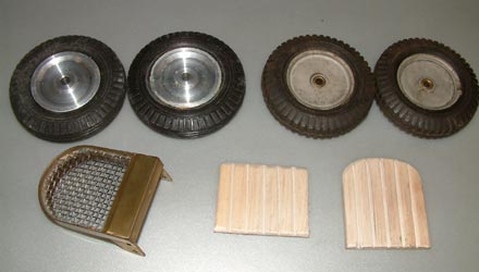
The original Wasp had part of the dummy seat with the squab missing so this and a complete set were needed for the rebuild. Balsa 3/16" sheet had been used for the seat back, so this was replicated with grooves cut to simulate cushion pleats and the whole covered in self-adhesive black vinyl sheet folded over the edges. The seat parts were glued in place within the cockpit opening in the body rear end using JB Weld a two part adhesive that remains flexible and is fairly tough. I bought this for sticking carbon fibre on which it also worked well. I am now just awaiting return of the dummy radiator after nickel plating and the car can then be finally assembled. Left: Dunlop replica tyres on solid hubs and some close replicas plus dummy radiator and seat parts. |
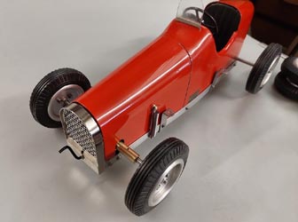
Final assembly of the M&E Wasp, resurrected from a box of
assorted bits.
 |
 |
©copyrightJohnGoodall/OTW2025