|
Home Updates Hydros Cars Engines Contacts Links ←Previous Next→ Contact On The Wire |
John Goodall on The Birth of the Oliver 'Tiger'
and further Oliver projects
|
|
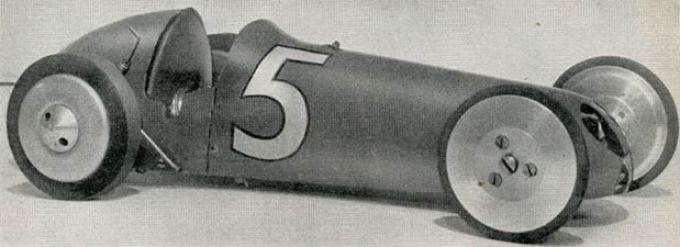
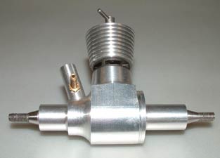
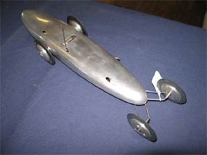
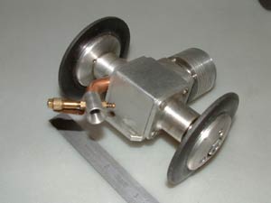
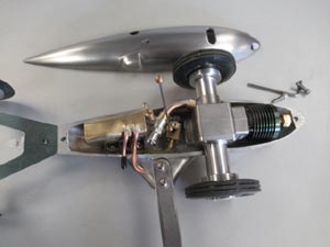
OTW: In 1949 the Oliver's were invited to Sweden as part of the British team for the return leg of the Anglo Swedish match races. Aware of the speed of Gerry Buck's Elfin powered car, the Olivers built an entirely new twinshaft engine in just three days that was a radical departure from their previous sideport Nine Port and Jaguar motors. It was quickly installed in 'Busy, seen here before being taken to Sweden by JSO. Such was the immediate success of the engine that orders piled in, so creating the legend that was the Oliver Tiger. Production versions of the engine differed considerably and the original vanished long ago so here, John Goodall describes the building of a replica of this iconic motor. |
|
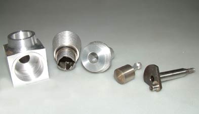
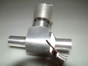
During the last few cold spell months I have been trying to find machining work to do, as my main workshop has no heating and I have some background storage heating where my machinery is installed in an insulated area, so keeping the chill off for a more pleasant environment. I thought I would have a further attempt at the prototype Oliver engine which eventually became the Tiger MK1. My first attempt with a front rotary valve was based on the Rustler Tiger Mk1 aero engine, so that I could use the aero engine crank shaft and cylinder assembly, I decided to use this replica Tiger as the start point for a more accurate prototype replica. It should be borne in mind the original prototype engine was built in a great rush, in about one week only and short cuts may have been taken purely to get a result in the time available. Is this why it did not survive I wonder, simply serving the purpose and then being scrapped? To me it was a priceless piece of history? Right: The start point |
|
|
|
Discussing this with Hugh Blowers, certain characteristics were seen as most likely, the most obvious being a disc valve induction system because the first few engines were of this configuration. The next was a very narrow angle to the venturi intake of 30 degrees from the crank shaft alignment which Hugh thought it should be from photographic evidence. Later production engines were set at 45 degrees, so I compromised at 35 degrees! I think now Hugh may well have been correct, because if you look at some of the early photographs of Busy which set the then new British Record at Orebro in Sweden in 1949, the needle is situated outside of the rear body. This however places the jet well outside the centre of the fuel tank as well and not desirable for fuel feed reasons in my opinion. Left: Pattern for disc valve taken from the only original DV motor known to exist |
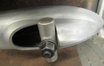
The other very obvious design feature was the mounting system using "U" bolts and axle support blocks featured in the earlier engines and here I later had a problem when mounting the engine in the next "Busy" body. The 35 degree angle I had chosen for the venturi restricted moving the support block sufficiently inboard to clear the body side. At the later 45 degrees it would have been easier. So I ended up having to machine a step in the block on the venturi side to overhang the chassis. I also had to file away the block to clear the venturi body. I think the Oliver's must have had an even worse installation problem here as well and may explain why production engines eliminated some of these expediencies, with the improved foot mounting and the venturi set at 45 degrees.
|
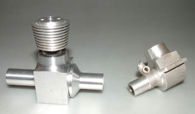
I commenced by stripping the Tiger Mk1 aero engine replica and making sketches of the crank case dimensions needed and cut a block from HT alloy to suit the main case and slave housing which was to be screwed into the main case body. I made the slave shaft housing first so that I could use the male fixing thread to gauge the female thread in the main crank case body later. All fairly straightforward turning with phosphor bronze bushes made and pressed in for the main shaft bearing surfaces. I did extend the bearing to cover the face of the disc valve seating to give an improved seal hopefully? Alan Knight kindly agreed to make the crank shafts for me at this stage provided I left some material in the bores for him to finish to the fit needed later. Right: Comparison of cases |
|
The main body was set up on a four jaw chuck with packing pieces to avoid
damage to the clamped surfaces. I machined the crank case bore and main
bearing bores in one operation to maintain alignment. Then screw cut the
thread for the slave shaft housing which I made it imperial as it would have
been in 1949. I next mounted the case at exactly at 90 degrees to machine
the cylinder fixing bore and retaining internal screw thread, which had to
be screw cut to match the cylinder fixing thread which is metric on this
Rustler replica. It turned out to a very good fit. I used to enjoy screw
cutting during my apprenticeship now well over seventy years ago, blimey
that long?? The outside body taper was now also machined, scaled off the
aero engine and slightly increased for additional strength.
The outside nose area of the main housing was now machined using an
expanding sacrificial mandrel which you can buy very cheaply from model
machine tool suppliers like Chronos and the best way of attaining concentric
accuracy. The outside diameter is turned after mounting in the three jaw
chuck, to the exact size of the main body bore. The body is then mounted on
this this to give the accuracy and the mandrel socket screw tightened to
grip the body for machining the outside. This can now be turned and will be
concentric to the bore. I again made a phosphor bronze bush for the main
bearing surface leaving approx. 0.005" for later finishing.
|
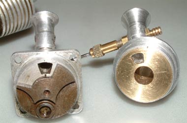
I now turned attention to the venturi and decided the NV position needed to be as close inboard as possible for fuel feed reasons. The fixing thread was governed by the maximum size I could accommodate in the housing and was 0.250" OD x 32 TPI with a bore of just 0.190". I was not convinced I could increase this overmuch to increase performance at the expense of minimum wall thickness? I next screwed the slave housing into the main body as tight as I could get it without incurring damage and marked for the venturi position in line with the cylinder axis but 180 degrees from the aero engine. I also had to think how it would be tightened for final assembly and decided to machine two flats to take a suitable spanner. Right: Trial assembly |
|
The intake housing was next machined setting the case at 35 degrees on an angle plate on my milling machine to machine the venturi fixing and intake port to a theoretical depth? This proved tricky and time consuming as it had to be correct. The main difficulty is it has to be machined to meet up from two different directions with the connecting port machined from the flat inner face at the appropriate radial distance to the theoretical point in the housing. The junction had to be filed using riffler needle files to gain a smooth transition. This proved very tedious and time consuming overall with the equipment I have and I now know why the Oliver's soon changed to a Rotary Valve on later production engines, as they would have had similar equipment to mine with consequent time penalties. A luxury you cannot afford in commercial production.
|
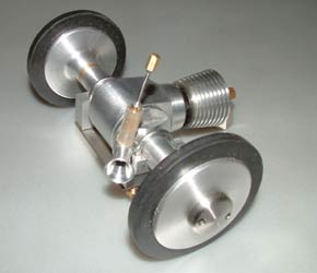
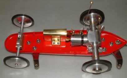
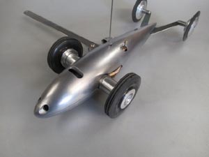
I posted the basic engine off to Alan at this point and started on making the main drive wheels. I wanted these to look more like those on the original Busy than my previous replicas. However the only tyres I had in stock which might be near enough were rather narrow resulting in even narrower wheels and this left insufficient room to sink the retaining nuts into a counterbore, as the originals had been made, so my retaining nuts ended up rather exposed, but "end on" look the same.
I decided front suspension is
needed on all cars I build to run in the UK because of the track
surfaces and I used a simpler variation of that on my previous Busy
builds. It comprises a channel machined in brass to give a bearing
for the pivot pins, with alloy "Z" shaped axles spring loaded off
the channel bottom inner face in locating counterbores. These were
milled and turned in the four jaw chuck. The pivot pins are retained
with a grub screw in the axle. |
|
|
|
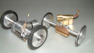
A steel pin is pressed into the lever end to prevent the spring sliding off. Springs can always be adjusted after trail runs, whereas rubber in compression as on my Vanwall is more difficult? I again made the wheels with little tyre rubber exposed to keep to the original lean look as closely as possible. The screws were fitted from the inside because of greater material depth on the outside.
After
getting the engine back with its new crank shafts fitted and nicely free to
turn I made the brass spacers seen on the disc valve ex Gerry buck engine. I
used this engine for the disc valve design incidentally assuming it would be
very similar. The spacers restrict end float and make sure that the disc
valve has a reasonable seal. They are currently set up with minimal end
float and may have to be adjusted if the engine tightens when it gets hot? |
So there it is, having taken much longer than the original to make, even with the donor cylinder assembly, but as close as I can reasonably get to it, I cannot wait to run it now? The next Busy replica car is finished and being painted at the stove enamellers I use in Burton upon Trent, Dumelos who are very good for all stoving and powder coating work.
 |
 |
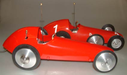
| The finished replica of Busy with the replica prototype Tiger twinshaft | |
Oliver Tiger twinshaft variants.
 |
 |
 |
| Prototype with Disc valve motor | Prototype, DV. RV. RVB. | Rotary Valve. Rotary Valve Ball Raced. |
The photographs above show the evolution of the Oliver twinshaft that culminated in the much more common Tiger twinshaft MKII. The prototype fitted in Busy has never been seen again, next is the Disc Valve motor of which only around three were built, then the newer Rotary Valve version and finally the ball raced rotary valve motor. Serial numbers are prefixed DV, RV RVB respectively.
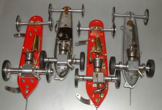
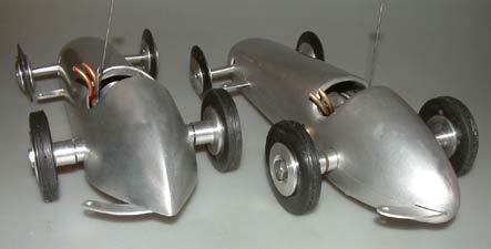
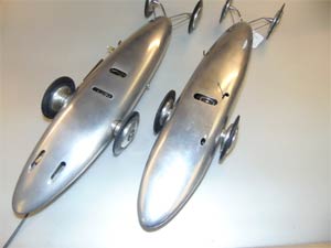
A 'Brace' of Busys
Photos John Goodall.
Text OTW
John is a great enthusiast for
anything relating to the Oliver family and what they have produced over
the years. Unfortunately none of their early cars are known to exist,
although there are numerous examples of their production versions. One
of the most intriguing was 'Busy', which used the prototype of what was to
become the world famous 'Tiger' twinshaft to such good effect. This car
was sold to Harry Howlett and became the basis of the first cast
'Oliver' car. John made the decision to recreate this iconic car, but
faced a dilemma. Only photos of the original car existed, yet the
published plan showed an entirely different layout, so what to do. Well,
John being such an enthusiast, why not make both. Not only was this
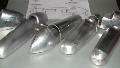
quite an undertaking as each had to be formed, by hand, from sheet
aluminium, but John very kindly offered to make a few 'extras' for
select 'friends'. The
OTW version has already been described, but here
are John's pair of Busy replicas.
 |
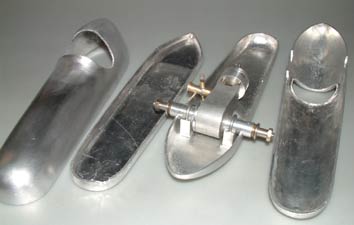 |
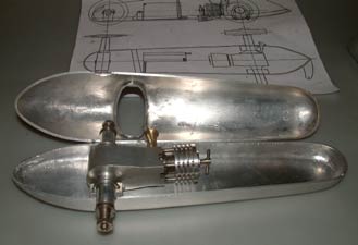
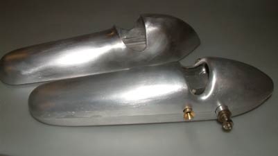
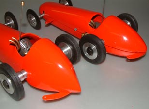
On the original car the top half of the body overlapped the pan completely with a joint at the front of the cockpit cut out. The plans show the top half of the body flush with the bottom half and the joint about 3/8th of an inch up from the bottom of the pan. Being and ex design engineer, John decided to go one stage further as it was not a true replica and make the joint line through the centres of the axles, avoiding long slots in the upper body that are evident in the prototype. Above can be seen both styles with the further addition of the cockpit surround on the MkII being turned in to make a nicer shape and provide more strength.
 |
 |
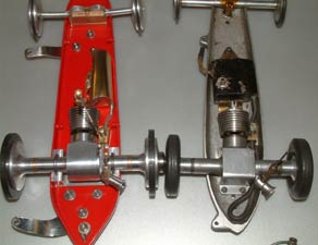
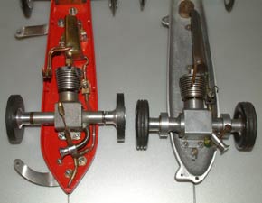
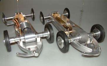
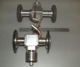
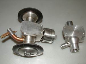
Engine choice provides a series of interesting options, but comes down in the end to what is available. Busy was originally fitted with a Jaguar twinshaft and then with the prototype Tiger, which still used U bolts to hold the motor down. The only RV or RVB motors known to exist are in cars and, as we know, trying to find Oliver or Olive style twinshaft motors is nigh on impossible. John was in exactly the right place when the original Oliver 'Nine Port', seen on the left became available. The motor on the right is a 'Rustler' reproduction Jaguar with a second crankshaft added by John.
 |
 |
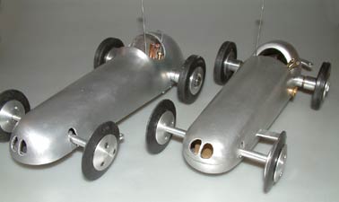
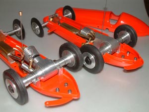
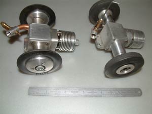
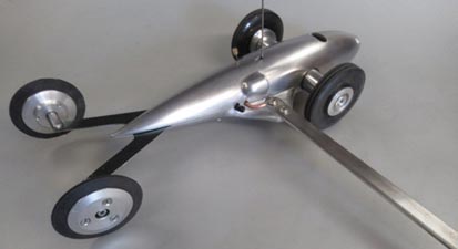
Above on the left is the closer replica with the Jaguar motor and the rear tether bracket coming through the pan flange. The independent front suspension is an engineering tour-de-force and a matter for speculation as the plan shows a pivoted beam axle, but with no idea if there was springing of any sort.
 |
 |
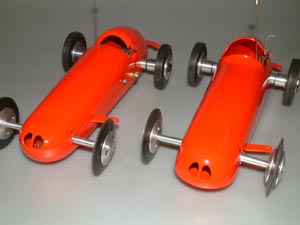
| 'Busy' MkI on the left with the enveloping body and the MkII on the right with the flush body and joint line | |
The finished 'Busy' One and 'Busy' Two replicas, now finished in red stove enamel,
 |
 |
 |
Unique 'short shaft' Oliver motor
At the auction of the Oliver Collection in 2017 I had managed to secure the unique Slabang that John S. Oliver had built. John had accompanied me to Orebro in Sweden where he bought the chassis castings and other parts for this car off Ulf Ek. Ulf Ek incidentally was co-driver to Stig Blomqvist when they won several World Rally Championships in the Audi Quattro. The significance of the Slabang is that it was the last car and also the last engine that John Oliver made! It was also the last car he would ever run, again at Orebro on his final visit with me to Sweden. The engine is made specially for the car with non standard mounting and a narrow track of 78mm, the production engines are 102mm track. I feel privileged to be its custodian for a while.
 |
 |
 |
| Standard looking Slabang | Until compared with an original | Nearly 1 inch narrower |
It is interesting to note the different fixing detail and the much narrower track to reduce frontal area. As well as the significantly shortened shafts and housings on both sides John reduced the height of the motor by machining the mounting foot flat instead of the more usual angle, reducing its thickness and having the motor mounted to the pan by two screws instead of four. The porting is typical flared Oliver tuned type, but all else is as the production engine mechanically. The early MkII crank cases were machined in the lathe and had a central relieved recess as shown on one of my replicas, later cases seem to have been milled on the base. One other thing of interest is the flats on the compression screw are stamped and numbered one to six, presumably to give an indication of setting.
 |
 |
 |
| JSO version and standard Tiger MkII | The JSO short shaft Tiger | Standard foot and JSO modified version |
Building the rarest of the Oliver cars
The 'Bomb'
with
Redfin twin shaft No 90.
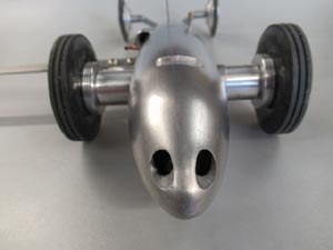
My latest Oliver car finished at last after several years since I cleaned up and jointed the body. I wonder if it was designed to accommodate the Mk1 Twin Shaft Oliver which might just go within the body, The Mk2 certainly will not. The Redfin being very slightly more compact will as can be seen, it is still a tight squeeze to fit the cut out and fuel tank in the cramped space. The rear wheels are mounted on stub axles riveted to the spring steel axle, which I hope will give some compliance at the rear end. I made a curly carb from Tungem tubing and silver soldered ferrules to mount on the engine and the original peripheral jet carb. A pan handle and mount were made which is screwed and finally welded onto the lower body half just behind the front drive wheels. The fuel tank is as large as I could get into the space, plenty big enough. That completes my line range of Original Oliver Model Car bodies, unless one more gets added to the line up?
 |
 |
 |
| Minimal frontal area | Not much room to play with? | Functional to the last |
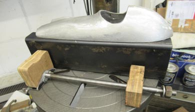
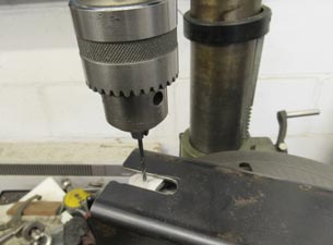
Drilling Jig for Oliver style casting sets
I have made many Oliver cars from the available castings and quite a few duplicates and on scale cars I much prefer to fix the two body halves together with screw heads below the chassis, so that they are hidden from a static view of the car. The difficulty with this is the problem of holding the inverted body top with the joint face square and parallel to the drilling machine table? The differing body shapes are not easy to support with vee blocks or anything similar.
There is always a better way to do
things and I have at last found an
improved way of holding the top using a
simple and fairly easily made fixture.
It uses a steel folded box section. Two
slots are milled into the top for access
to the pre-marked hole position after
first drilling the chassis making sure
the holes to be tapped in the top are
located in a substantial cast part of
nose and tail. The fixture slots could
easily be hacksawed into pre drilled
holes and filed to finish if you wish to
make your own and have no milling
facility. I used 1 inch thick plywood
off-cuts for the two support blocks
easily cut and drilled and do not mark
the body. The draw bolt is a piece of
steel bar 3/8” to 7/16” diameter and I
attached one end to a scrap piece of
steel 1” angle section as I needed a
little more height on the nose block,
the other end threaded with a Whitworth
thread for speed of adjustment and
passes through a clearance hole in the
tail block.
 |
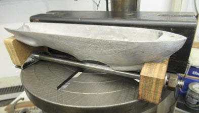 |
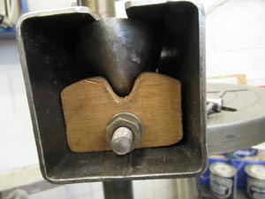
In use the inverted body top is placed on the wooden support blocks, the assembly inserted into the box section, aligned with the two slots and the nut nipped up by finger, which sprags the body to the inside top of the box section. This finger nip of the nut proved adequate in practice to hold it firmly against the top for drilling and tapping. No more possible movement or mis-alignment giving tapped holes at in appropriate angles leading to scrap or repair.
 |
 |
 |
I am offering the fixture on loan for free to anyone wishing to build an Oliver model car and who has bought the castings off Ian Harper, but you will need to arrange delivery/return, or collect and deliver back to me, or Ian Harper please.
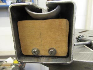
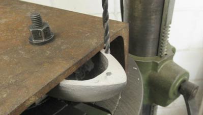
A 'Simpler solution'
I made a simple jig this morning in
about twenty minutes. This is to
accurately drill and tap the body fixing
holes in model car bodies. The idea is a
much simpler idea based on my previous
one and consequently much easier for
those with less facilities to make, it
only requires drilling one hole in a
suitable piece of channel section and a
cross clamp ditto made from a small
length of round ally bar to avoid damage
to the body. I used the bolts and two
nuts off a clamp set for the clamp. A
bench drill, or pedestal drill keeps
things dead square.
 |
 |
©copyrightJohnGoodall2025