|
Home Updates Hydros Cars Engines Contacts Links Racing Contact On The Wire |
|
|
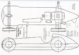
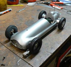
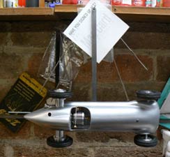
Oliver Monk A Car for Buckminster |
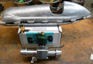
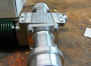
I have chosen one of the John Oliver cars, the Mercedes, these are from castings that are supplied by Paul Ironmonger. The engine is the new 2.5cc diesel twinshaft from Redfin Engines, as is the shut off. The build will be table top, you won’t need a machine shop, but it would make life easier. Contact details for parts, tools and fixings at the bottom of the article.
 |
 |
 |
|
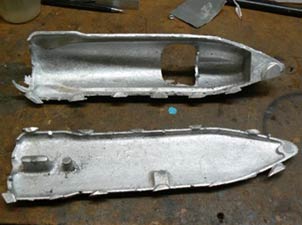
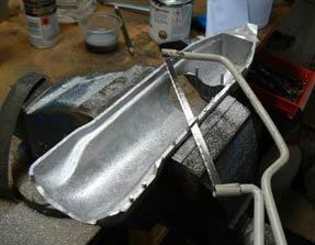
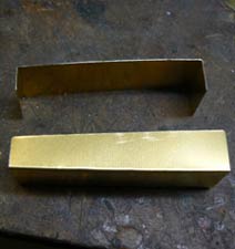
Raw Oliver Mercedes
castings. |
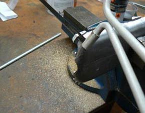
The first job is to remove all the flash from the castings a junior
hacksaw |
|
 |
 |
 |
|
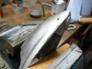
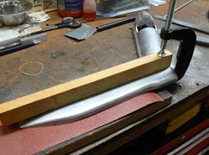
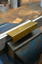
Hold the bottom down with a G clamp onto the bench so you can file off the flash. |
The top is best held in a vice as it’s an awkward shape. |
Just showing the flash removal. |
 |
 |
 |
|
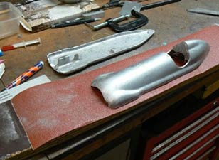
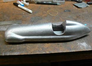
Flash removed from the top casting |
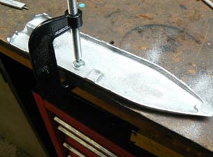
The
bottom of both castings need to be flat, I use a flat board and
100 grit abrasive paper. |
|
 |
 |
 |
|
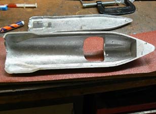
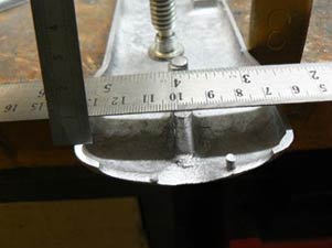
To make the bottom easier to push I clamped on a piece of wood. The bottom is not so easy to do as parts of the casting stick out beyond the bottom. Get the bulk of the bottom flat then do the front, one side at a time, checking the fit with the top. You may have to use a long file as well to get it right. |
The two castings are held together with screws one at the front and one at the back, I’ve gone metric so they will be M3. Scribe an arc from either side of the bottom to find the centre then centre punch in the middle of circle. |
|
 |
 |
 |
|
Drill the hole 3.1mm diameter. |
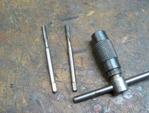
Line up the two castings and hold together with G clamps. Using the 3.1mm drill make a small indent (spot) and then drill the top with a 2.5mm drill about 10mm deep. Tap the hole M3. Aluminium can be funny stuff to tap, easy to break the tap if you are not careful, use WD 40 as a cutting lubricant. I use a small tap holder, then I cannot use too much force. |
|
 |
 |
 |
|
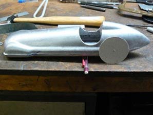
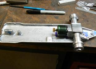
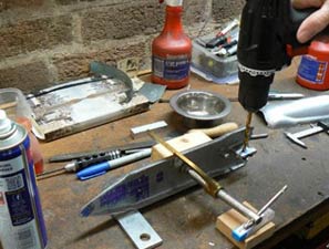
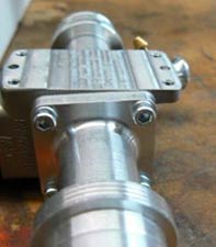
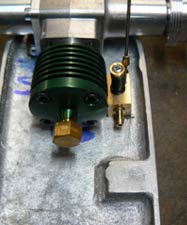
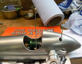
Fitting the engine is next. The first picture is from "The Oliver’s and a Tiger", be careful using the drawings as they are undersize. The wheels have not arrived yet but they will be 2 ¼" diameter. The cardboard wheel is to get the axle centre line right. |
Make sure your centre line across the bottom of the pan is square, check from both sides. The pictures are a bit out of sequence, file out the bottom sides so the engine fits and sits in the bottom of chassis. |
|
 |
 |
 |
|
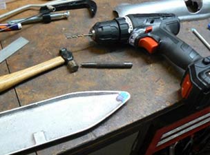
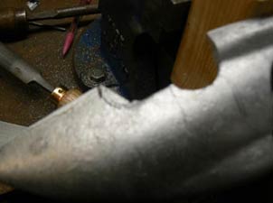
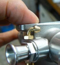
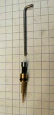
The needle valve assembly will have to be removed as it sticks out below the bottom of the engine. |
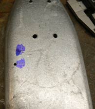
Mark out the hole positions from the centre lines,
centre punch and |
|
 |
 |
 |
|
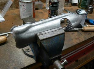
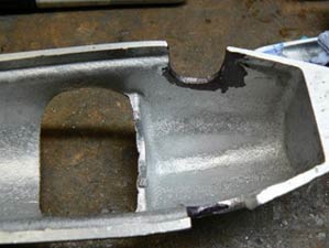
With the engine in the chassis it now time to start fitting the top. Use a long bolt in the back of the car to position the top and put some packing in the front of the car so the top sits parallel to the bottom. Mark the axle position. Also mark the top of where the axle goes and make a little template to mark the rounded top. |
The top will take a bit of fitting. The black marker pen is so I can see where the engine is touching. |
|
 |
 |
 |
|
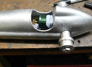
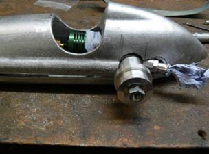
The top finally on. Note the paper towel in the exhaust and intake to keep the swarf out of the engine. |
Put the venturi back in the engine and fit the top.
|
|
 |
 |
 |
|
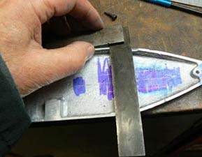
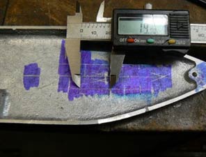
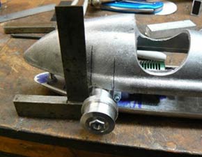
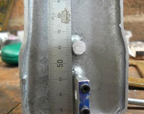
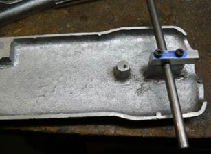
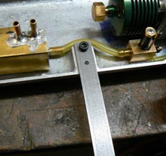
A hole is required in the top for the needle valve. Use the square to line up with the centre of spray bar, mark the bottom chassis, then note the distance to spray bar centre. Put the top on, line the square up with the mark you made and then use the dimension you took to mark the hole in position in the top. |
File the top of the front suspension lug flat. |
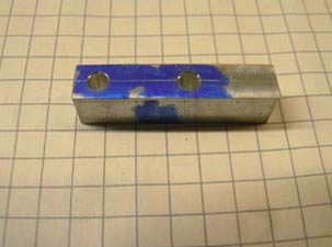
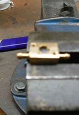
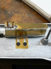
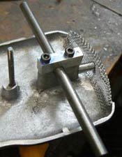
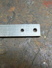
Check the lug is filed flat by checking the height above each side of the chassis. Using a piece of bar make a clamping block 8 x 6.5 (1/4") x 30mm. Drill two holes in the centre 15mm apart 3. mm diameter. |
 |
 |
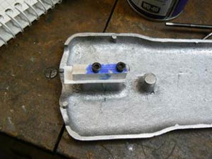 |
| This is the top half of the clamp for the front axle. |
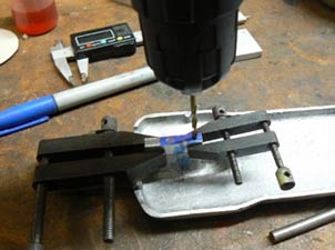
Hold the top half of the clamp in place and spot through the two holes, then drill the two holes 2.5mm diameter and tap M3. Put a piece of paper between the top clamp and the lug and bolt up. |
|
 |
 |
 |
|
Mark the axle position along the joint line between the lug and clamp and the centre between the two bolts, then centre punch. Set up the chassis as in picture. The block of wood will keep it square and pack up the back so the chassis is parallel to the bench. Drill a ¼" diameter hole (that was the size of my axle 6 or 7mm would also be OK) keeping the drill square. If you have access to a bench drill that makes it a lot easier. |
Fit the front axle the same way as for the rear one. |
|
 |
 |
 |
|
Slots cut for front axle. |
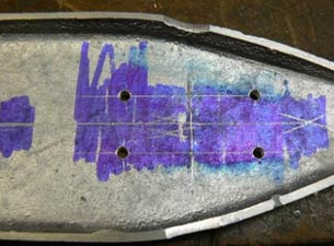
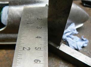
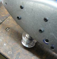
For the front hold down bolt stand the bottom up vertically on the bench and measure to the centre of the round lug. Put the top on the car and transfer the measurement to the top of the car then find the centre of the top mark and centre punch. Make sure the top and bottom are lined up and drill through with a 2.5mm drill. Remove the top. Drill the 2.5mm hole about 10mm deep and tap M3. Open the hole in the top to 3.1mm. I didn't quite get my measurement right but it will work fine. I didn’t have a bolt long enough to bolt the top on at the front so made a stud. |
|
 |
 |
|
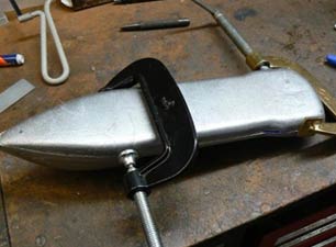
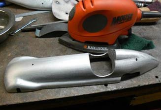
Bolt the top and bottom together. File the joint line smooth between the top and bottom, then clean the castings up. I have used a palm sander, starting with 80 grit paper then 120 grit. After that it was done by hand with 400 grit wet and dry paper. I am not going to paint my car; I went to the Goodwood Festival some years ago where they had the Mercedes Silver Arrows, they were not painted. I have finished the car using a green abrasive pad on the palm sander, it gives a nice matt finish. |
|
A Car for Buckminster continued
 |
 |
 |
 |
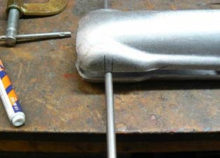
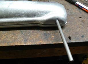
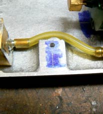
The spray bar protrudes below the bottom of the engine this means you cannot mount the engine flat in the pan. Remove the spray bar from the engine, with a file reduce the diameter of the spigot that the fuel tube goes over is too big. The next bit is to bend it round as in the second picture. I did this by holding the spray bar with a pair of pliers, have a piece of wire that is a good fit in the end. Heat up with a gas torch to dull red, put wire in and bend. It may take a couple of goes to get it as shown in the picture. I was told I was lucky to do it, will find out soon as I have another engine to do.
Still on the spray bar. When you put it together facing the right direction in the car you may find there is no hole for the fuel to come out of. Mark the position with a black marker, on my spray bar the new hole was directly opposite the existing one. Drill through with a 1mm drill.
 |
 |
 |
 |
|
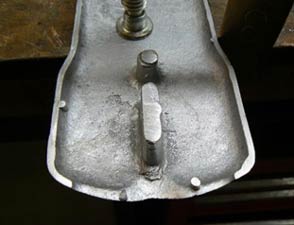
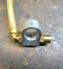
Position the shut
off in the bottom of the pan, ensure it clears the cockpit and the
engine. Transfer the hole positions to the underside of the car
by the
same method as the needle valve hole. Drill 2.1mm holes. |
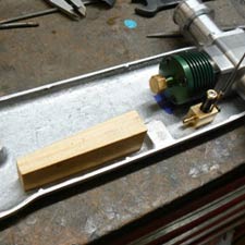
File the base of the shut off so that it fits the bottom of the car, the arm vertical. Next make a dummy tank out of wood, it needs to be as close to the side of the car as possible. | ||
 |
 |
 |
 |
Fold the brass sheet up to form the tank, you can also use the dummy tank to fold round. Drill the holes for the vent pipes and the fuel feed before soldering together. The tank is 70mm long, 20mm tall, 15mm wide at the front and 10mm at the rear.
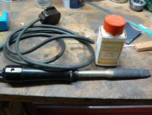
The car will run anticlockwise so the fuel feed is on the inboard side of the car, tank position is important being able to move the tank is useful. Note the big old soldering iron, it helps to have plenty of heat when soldering tanks, I like Bakers fluid but it needs washing off with water when you have finished. Check the tank for leaks, I block the two vents with my finger and suck on the fuel feed pipe, stick your tongue on the feed pipe it should hold a vacuum.
 |
 |
 |
 |
| Needle modifications | A bit of adornment | ||
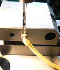
The needle valve sticks out way too much, when you shut down the car the brush will bend the needle. A lathe makes this easy to drill down the middle of an M3 caphead bolt, cut the excess needle off and use Loctite retainer to glue it together. I also turned down the head of the bolt.
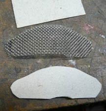
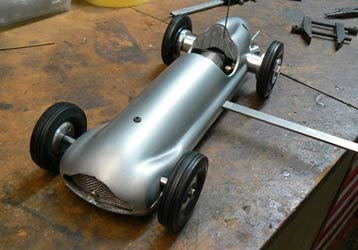
Above right: This is nice to have, won’t make the car go any faster though. Cut a template for the grill a bit on the big side then cut round a piece of stainless mesh and fold the edges over with round nose pliers until it fits the car. Drill and tap the front suspension mount M3 and use a piece of tube as a spacer and use this to hold the grill in place.
 |
 |
 |
 |
|
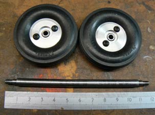
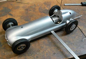
I have pinched some wheels off another car, it's starting to look the business. On the right I have countersunk the holes for the shut off. I always found this difficult so the option is to use button head screws they look better than capheads. |
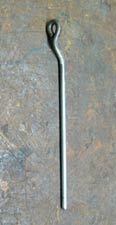
Bend up a skid out of piano wire, heat the end to red hot and form the eye, drill an elongated hole and fit the skid. I need a longer bolt and a Nylock nut. | ||
 |
 |
 |
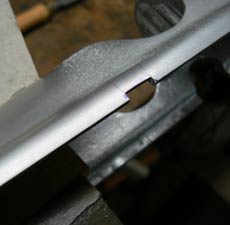 |
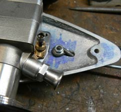
Drill all the way through and tap the raised block in the casting M3, fairly close to the end. The tether arm is made from a piece of mild steel bar. The dimensions are attached at the end of the article. Drill one hole at the end 3.1mm and the inner hole 2.5mm. Fix the tether arm to the chassis set at 90 degrees to the car centre line, spot the hole through, drill and tap M3 and drill the hole in the bridle 3.1mm. Mark out and file a slot for the tether arm in the top.
|
|
|
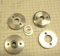
The front axle and hubs require the use of a lathe. The axle ends are 5mm diameter to fit the ball race and the thread is M5. I made a mistake making the hubs and had to cut a recess and make a washer to save them, they would only normally be two halves. |
The balance of
the car is important it needs to hang with the front of the car
pointing out a little. I have used wheel weights in the front of
this car, they come with self adhesive backs. It also needs to
hang so all four wheels are on the track.
 |
 |
The shut off lever has been bent so that it does not hit when the car is being pushed off.
 |
 |
Well that’s it, the car's finished already to run, we have a track that is almost ready to run on but we cannot go out and play at the moment.
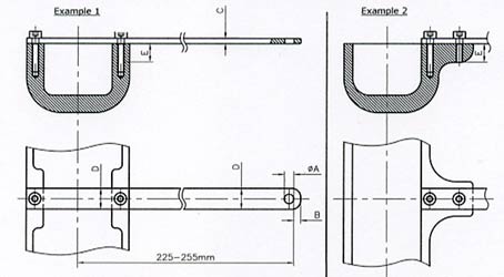
Bridle dimensions for 2.5cc car
|
Class |
A |
B |
B |
C |
C |
D |
E minimum |
min. 2 |
Safety factor |
|
min. |
max. |
min. |
max. |
min. |
screw length |
screws |
|
||
|
2 |
4.5 |
2.5 |
4 |
2 |
3.5 |
9.5 |
9 |
M 3 |
2.35 |
|
Screw qualities: 8.8 No countersunk screws |
|||||||||
|
* Tensile strength at yield 500m/mm2 All others Tensile strength at yield 250m/mm2 |
|||||||||
Contact detail for the sources of supply of all items mentioned
in the article. OTW and Oliver would like to make it clear that
these details are for information only and do not constitute
personal recommendations. Any transactions are strictly between
builders and individual suppliers.
Oliver Style Mercedes castings.
Paul Ironmonger email
ironmonger619@btinternet.com
Redfin twinshaft motors, fuel cut offs
Alex Phin email
alex@redfinengines.com
Nuts and bolts
GWR Fasteners
https://www.gwr-fasteners.co.uk
Tools, files, drills, taps etc
ARC Eurotrade
https://www.arceurotrade.co.uk
Help Line
Oliver Monk email
oliver.monk@btinternet.com
©copyrightOliverMonk2020