|
Home Updates Hydros Cars Engines Contacts Links Contact On The Wire |
Easy build tether car chassis by Paul Harris
 |
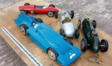 |
| Auto Union at Old Warden | Ferrari, Bluebird, Auto Union, Cooper Bristol |
|
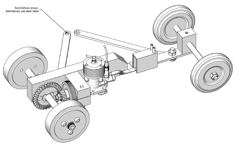
The same, easy build chassis was used for all the cars above and is based around the bevel gear set from a 4" angle grinder, and a model diesel engine with rear induction (giving a parallel front crank case for ease of mounting) i.e. Russian MK17-rhytm 2.5-KDM-ED etc. I have found that a geared drive system has the advantage of larger slower rotating wheels avoiding the necessity of vulcanised tyres. A geared engine is also much easier to push start. |
|
|
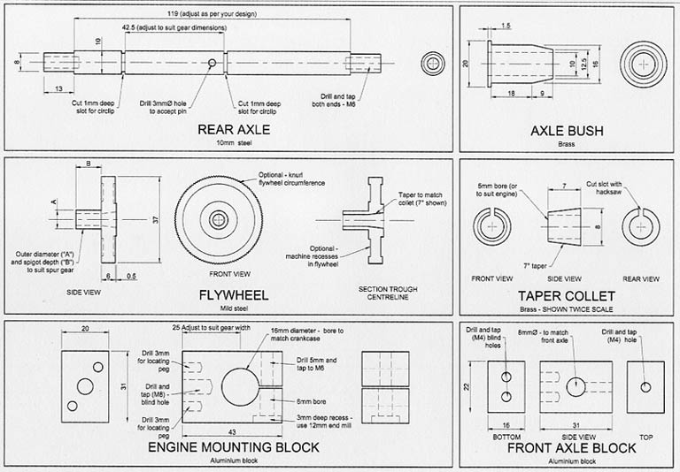
The rolling chassis was designed to be built with minimum equipment: only a small lathe (three jaw chuck) and a pillar drill. The engine mounting housing and axle bush drillings were made with a reduced shank 5/8" blacksmith drill, avoiding the use of boring bars or reamers. New angle grinder gears are available from the internet (eBay or try useful&rare.com for dimensions) at very little cost (£6-12). For 1.5cc engines, the set from a 100mm angle grinder (with the pinion bore of 8mm) are required, and for 2.5cc engines (with the larger 6mm crankshaft), the gears from a 150mm angle grinder with 9 or 10mm pinion bore are best. There are many slight variations in gear ratios/size, so the dimensions on the drawings are only approximate. Please check with trial runs before cutting/drilling! |
|
The Russian MK17 engine, although heavy for a model aircraft, is excellent for tethered car use. It is best to bench test-the engine, with a propeller fitted, to check all is well and have some basic settings for compression/needle valve before preparing for fitting to your car. The prop drive and collet should be removed as this will be replaced by the flywheel. The crankcase around the front bearing housing should be filed round and as parallel as possible. (or machined if you have the facilities) |
 |
 |
 |
|
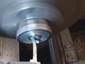
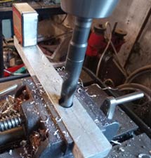
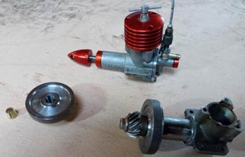
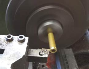
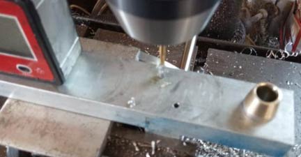
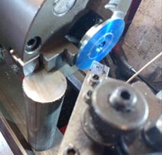
Above left: drilling the main holes for axle bush and engine mount, with a blacksmith's reduced-shank drill. Centre: MK 17 with prop drive removed and replaced with flywheel and gear. Bearing housing filed to remove casting marks. Above right: external collet taper being machined with same top slide setting of 7˚. |
|
The only parts requiring accurate machining are the flywheel and crankshaft collet. The flywheel is machined from 38mm (1.5") EN1A mild steel or similar. Firstly machine down to suit your gear pinion (8mm diameter for MK17) and cut to length. Reverse in chuck, centre and drill to suit crankshaft (5mm for MK17). The internal taper for the collet should now be cut with a small boring bar (6mm tool steel, ground to suitable tip) with the top slide of your lathe set at 7˚. Remove the flywheel and mount a short piece of brass/bronze/aluminium in the chuck for your collet. Cut the external taper of the collet without resetting the top slide to ensure a good fit into the flywheel. The collet can then be drilled to suit your crankshaft, cut off and slot. Right: Machining the internal taper in flywheel at 7˚ |
|
 |
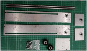
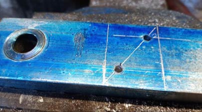
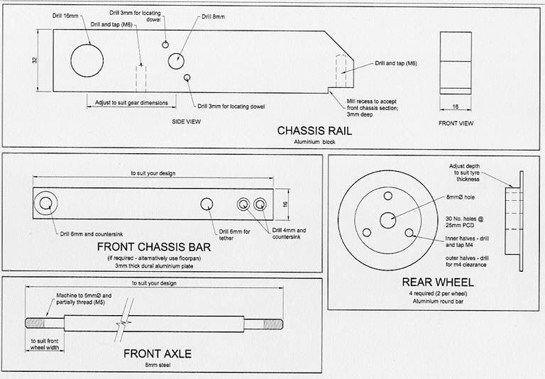
The engine block is a simple piece of aluminium drilled (I used the 5/8" blacksmith drill as the reduced shank would fit in the small pillar drill) to suit your engine crankcase. Drill and tap for the clamp bolt before slotting. Note that the crankcase should have 2-3mm lateral movement in its mounting block to allow adjustment for gear mesh. The main chassis rail may be the full length of the model or just a short "sub-frame" to be fitted to a floor casting/pan/extension plate. The hole for the axle bearing should be drilled (I used the 5/8" drill again) and the axle bearing made a press fit into the rail. The next important job is to align the engine mounting block with the chassis rail. This is best done by temporarily fitting the crown gear to its axle bush with a 10mm (or to suit your crown wheel/bush) bolt. Left: Engine mounting location being scribed on to chassis rail. |
|
Place the engine mounting block (with engine/flywheel/pinion centrally clamped in place) on the rail with the gears meshing correctly. Scribe a line around the block so that when the block is removed two 3mm locating dowel holes can be drilled in the rail. The engine mounting block should then be temporarily held in place with 2 pack epoxy adhesive. The holes in the rail can then be used as a guide to drill the dowel holes in the engine mounting block. Finally fit 3mm dowel pins, and drill/tap for the main M8 fixing bolt. |
 |
 |
| Above Left: Using drilled holes as guide for dowels in engine mount. Above Right: Pilot dowel holes drilled | |
|
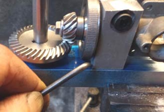
The axle is a straight forward machining job, the drive for the crown wheel can either be a simple 3mm pin or if a milling machine is available, a slot maybe machined and a woodruff key used. Please note that the length of the axle, the position of the crown wheel and the size of the tyres will be dependent on the type and size of the model you are making. Tyres are made from offcuts of reinforced industrial rubber sheeting. Staple the rubber sheet to a sacrificial block of wood, mounted to a pillar drill. Cut out the centre hole using a holesaw then without moving the drill centre line, cut out the outer diameter, again with a suitable size holesaw. The wheels can then be made to suit the tyres. The front wheels/tyres are made in a similar manner, but with the addition of an axle bush or bearing. |
 |
 |
 |
|
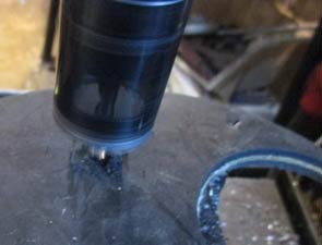
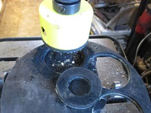
Rubber sheeting stapled to scrap wood Drilling central hole with hole saw |
Drilling outer diameter with hole saw | Marking out wheel bolts at 120 degrees, by locking chuck with bar against jaws |
|
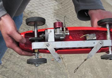
Assembly and running notes A 1.5cc powered car will pull a car of approximately 1.6kg. A 2.5cc car approximately 2.7kg The engine should face the outer side of the tethered circle and can be mounted vertically or horizontally We have available laser-cut crankcase gaskets for the MK17 The crown wheel pinion meshing can be adjusted by moving the engine fore and aft in its mounting block and shim between the crown wheel and axle bush until they run smoothly. |
|
The fuel tank can be made from central heating copper end cap fittings, soldered each end to a short length of suitable copper pipe (15mm for 1.5cc engines, 22mm for 2.5cc engines) The tethered cable bridle mounting should be at the balance point of the car. I have found the best method is to use mounting points at both ends of the chassis rail and use two cables which can be adjusted in length until the car tracks correctly. On the first push starts, the crankshaft nut WILL work loose. Tighten and retry several times until the flywheel/collet settles in, then glue with Loctite and will then hold. Body shell design and type can be made from wood glass fibre or aluminium at your discretion. |
|
|
I hope this article enables you to build a successful model car with minimum cost and maximum fun ©copyrightPaulHarris/OTW2022 |
A Simple Rolling Road for Tether Cars
Ian Wingfield
|
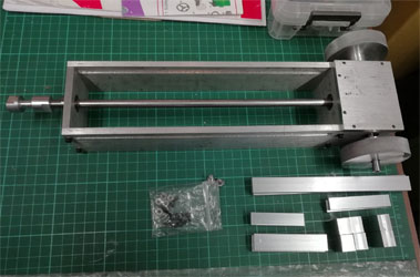
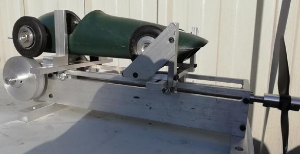
This came about after I changed fuel during a competition and couldn’t get my car to keep running, let alone perform. A fellow tether car runner, thanks Jan, sacrificed most of his lunch break to help me achieve working settings on the track. I thought afterwards that there must be a better method to find suitable settings without the push and hope experienced to-date. Obviously, there exists a society of masters who know the arcane ways of the diesel engine and to them this must seem trivial. However, having only ever run glow motors before, I need all the help I can get… A simple rolling road seemed to be what was required. This needed to be simple to make, adjustable to suit different sized cars and with some form of cooling built in. I decided to rotate the drive through 90 degrees and use a propeller to provide the cooling airflow. The propeller provides not just cooling, but also provides a variable load to allow the rig to be tuned to simulate track conditions. No drawings exist because it was made up as I went along using materials to hand. However, the principle is simple enough to see with reference to the photographs. |
|
As a guide, the length of the side frames is 340mm with a height of 50mm. The distance between the side frames was determined by the minimum size to mesh the gears with a small allowance for a spacer to ensure the gear hubs do not rub on the race outers. The actual size ended up at 62.26mm giving an overall width of 74.96mm because the side panels are ¼" (that’s why you have DROs on machines…) The gears were from Amazon – look for ‘Mxfans 2 x Modulus 1.5 Silver 8mm Hole 20T Tapered Bevel Gear Wheel with Top Screws’ or similar. |
|
| The gears determined the size of the shafts at 8mm. These were made from silver steel, straight and a good fit for the bearings. Simply Bearings supplied these 18 x 8 x 6, sealed to keep the dirt out. They were press fits into 5mm deep recesses bored into the frame parts. |
|
|
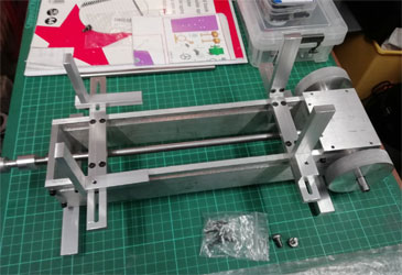
All shafts have flats milled where necessary to provide a solid location for the grub screws while making it easy to disassemble the parts in future should that be required. Originally, the driven wheels were going to be aluminium hubs with ‘car starter’ rubber rings as tyres. Upon reflection I thought that running these in excess of 10,000rpm might not be such a good idea and decided to use solid aluminium wheels. A light knurl was put onto these to aid traction. The end of the propeller shaft is threaded M6 onto which is screwed a prop driver which has a plain bored section to locate it centrally on the shaft and a screwed portion to retain it. |
|
It had to be easy to take the car on and off the road because it needs to be put in place with the engine running. As a result, although the front wheels are used to restrain the car they are not held rigidly. Any attempt to squirrel off the rollers is handled by two uprights located either side of the car just ahead of the rear wheels. These uprights are chamfered on the top half and covered in rubber strip to minimise the chance of any bodywork damage when placing the car in position. The wheel stops and uprights are mounted on slotted cross pieces, which, in turn, can slide forwards and backwards along the frames to offer the adjustability required to suit different sized cars. |
|
|
In operation, the speed is determined by measuring the rpm of the propeller using an optical tacho and then dividing this by a ‘magic number’. The magic number is the rpm that equates to a speed of 1mph. Given a 2.5” wheel diameter on the rig, this is ((1760 x 3 x 12)/(2.5 x pi))/60 = 134.454 Eg: At 10,000rpm the equivalent speed is 10000/134.454 = 74.37mph The rpm of the engine is determined by the ratio of the driving wheels to the driven wheels. Engine rpm = measured rpm x (rig wheel diameter/car wheel diameter) Eg: For 10,000 measured rpm, 2.5” rig wheels, 2.25” car wheels Engine rpm is 10000 x (2.5/2.25) = 11,111 rpm |
|
With the addition of an electric motor to provide a variable load, a load cell to measure the torque, a hall effect sensor to measure rpm and a bit of software to link it all together it should be possible to develop this into a dynamometer, but that is for another time… Rolling road video here (from about 3:20) www.youtube.com |
©copyrightIanWingfield/OTW2022