|
Home Updates Hydros Cars Engines Contacts Links Contact On The Wire |
|
For years I had been very keen to obtain one of these engines for my collection, and had all but given up any hope of ever obtaining one, or even seeing one in the flesh so to speak. Then out of the blue a few years ago I had the opportunity to acquire from a well-known UK collector the featured example. For some time OTW has been gently bending my ear to record my thoughts on this engine before they are lost to the mists of time, and dementia. The only recorded reference to date on these unusual engines is John Goodall’s cover feature article in the late lamented Model Engine World magazine, May 1995 issue. John at the time was only able to sketch out brief details of the engines spec, and history. What follows are my own personal notes, and details, which may go some way to shedding more light on this obscure slice of British model petrol engine heritage. |
|
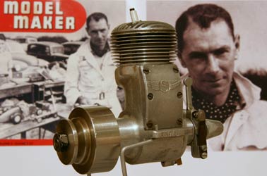
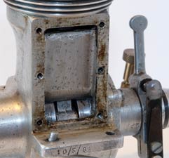
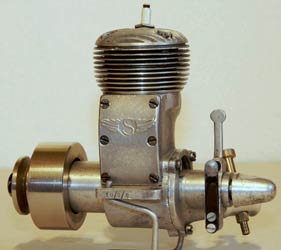
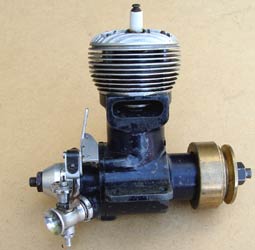
My Speedwell (left) dates from circa 1948 and is a rare survivor from the small production batch of approx 16 engines manufactured at Rochester in Kent by the late Ken Robinson. It is numbered 10/3/8 perhaps this may indicate the date made, or be some other numbering convention. The number 8 appears stamped on several component parts, so we can assume this was the eighth engine made. The individual numbering of component assemblies would also indicate the very one off manufacturing process in producing this batch of engines. The handful of surviving engines all exhibit detail and material differences. It was originally believed that only twelve motors had been made, but another engine recently examined (centre) has the number 10/3/16. This to date being the highest numbered example found, which makes the 10/3- element of the serial numbers even more mystifying?
 |
 |
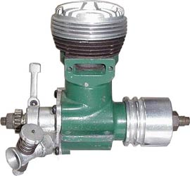 |
Looking at the photos from of the green painted Speedwell it too has a magnesium crank case. Painted like #16, I guess to help prevent corrosion. This engine looks like it may have been made up from the last of the bits. The logo is missing from the transfer, and an assortment of fasteners has been used to assemble it. Of note is the fact that fins and liner have been machined integral from cast iron. The cylinder fins on #8 replace the original water cooling jacket, whilst the head on #16 is a replacement for the one that was on the engine that had been filed to clear the HT lead, the suspicion being that the motor was mounted horizontally in a car. The new head is an original item that the late Mike Beech just 'happened to have' amongst his collection of obscure spares.
|
Ken Robinson of the Medway club will be a familiar name to many of our readers as he was a very active and competitive figure from the early days of the sport. Particularly in the smaller diesel tether car racing classes, 2.5cc, and 1.5cc. Ken designed most of his cars and engines himself, displaying a high degree of original design, and excellent workmanship in the manufacture. An example of Ken’s approach to car and engine design can be seen in an article from a 1953 issue of The Model Engineer magazine, which was also reprinted in issue No 8 of the Retro Racing Club’s newsletter. The article titled The growth of the "tiddlers" by Geoffrey Deason was a review of the 2.5cc class cars from 1948-1953, and featured the "Flying Flue" as it was nicknamed, or the R.T.D Special, with notes penned by Ken Robinson himself. |
|
|
|
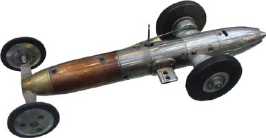
An original example of this car built by Ken came up for auction at the 1994 Christies sale. The car at auction had been extensively rebuilt from the remains of the original for Miguel de Rancougne’s collection. It should be born in mind that this was an experimental car and developed over many months of running and testing. It is also possible that Ken made more than the one example of the design? Although I do recall mention that the engine could be re-linered to both 1.5cc and 2.5cc class sizes. |
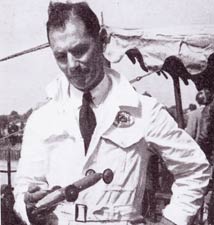
A photo of man and machine graced the front cover of the Model Maker magazine for October 1953, taken at the Chiltern M.C.C track at Woodside near Luton during that year’s national speed trials. The R.T.D Special (Robinson Thompson Design Special) was produced in conjunction with another Medway club member, and friend of my late fathers, George Thompson –interestingly both Ken and George in later years collaborated in the building and running of gauge 1 live steam locomotive models.
Ken Robinson worked in the aircraft industry during, and after WW2 at the Kent Alloys foundry at Strood in Kent – the factory being next door to the famous aircraft manufacturers Short Bro’s Strood extension, where my father worked in the early war years. The Kent alloys factory site has been recently cleared and levelled, no doubt for yet more housing!!
During those far off wartime days, in the summer months from 1940-42 the running of model hydro’s during the lunch break was a popular pastime with Ken, George, and my father. They would let their model hydro’s run free across a flooded area which had its banks built up to serve as an emergency fire fighting reservoir. The boats progress ending up being rapidly arrested in the reeds, and vegetation at the water’s edge. Ken’s model had an E.T.Westbury Kestrel 5cc petrol engine machined up by Ken from castings, Dad’s red painted single step hydro was powered by a pre war example of the Ohlsson 23. Sadly the identity of George’s model is now lost to the mists of time, but may have been a flash steam powered boat? As I recall dad saying it went like stink with an aggressive exhaust note when it could be persuaded to run!
Ken moved on post war to several local engineering firms, finishing up at the Metal Box Company in Rochester, where in later years he was involved in the training of engineering apprentices. He retired in the mid 1960’s? After the decline in the tether car racing scene, his interests and talents turned to full size Go-carts, and also small full size racing hydroplanes. And finally on to live steam in the shape of gauge 1 locomotives. He spent his final years in Scotland after the death of his wife Kath, living with his son Alan. (Special thanks to David Giles for much of the biographical detail above).
ENGINE DESCRIPTION
Around 1947-48 Ken Robinson, and my late father both ventured into the design and manufacture of 10cc racing car engines. Both were members of the Medway Model Engineering Club, generally referred to as the "Medway Club" At this period some testing and running of cars was carried out at a small brick built, circular, local track at Messr’s Shaves builders’ yard in Rochester. This was in a residential area and noise soon became a problem, particularly if anything more than Mills engine powered cars were run!!
It is of interest that dad’s Pioneer 10, and Ken’s Speedwell engines both share some features of design. The piston construction, the asymmetric four bolt head, and angled venturi. Chance design features, or shared knowledge? Sadly with the passage of time we can now only guess.
The Speedwell has many interesting points of design for an engine of this period 1948. Quite large and heavy by 10cc standards, my example weighs in at 1lb 6oz without its flywheel. This compares with a Rowell Mk1 at 1lb 3oz and the Pioneer 10 mk1 at 1lb 1-3/4oz. My Speedwell has aluminium castings; the magnesium cast examples are marginally lighter at 1lb 2oz.
|
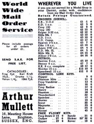
Of the three Speedwell engines we have had sight of, two have cast magnesium crankcases, and one cast aluminium alloy? This may have some bearing on the intended end use of the engine. Although primarily designed for car use, aircraft, and marine applications were also possible. It was fairly easy to convert to marine use by swapping the slip on air-cooled fins for a water-cooling jacket. The engine it seems was only advertised the once in a November 1948 advert in Aeromodeller magazine, sold by Arthur Mullet’s Brighton store. It retailed at £12, which was comparable in price with other 10cc racing engines available, none of them cheap at the time. Looking at the engines construction I have only partially disassembled my example for inspection –and it has revealed a few surprises. |
|
Starting with the lapped cast iron piston, liner combination, the composite piston has an alloy crown and wrist pin carrier, probably screwed together, securing the cast iron piston shell. The deflector top is gently sloping and contoured, at T.D.C there is no sub piston induction. The semi submerged cylinder liner is a good fit in the crankcase, secured in place by four long studs and nuts, these pulling down on the cylinder head and top of the liner securing the slip on fins, somewhat in the fashion of a Nordec. The cylinder head is machined from an aluminium casting, and is quite deep at approx 3/4" The machined fins being quite fine and somewhat fragile. At each of the four stud hole positions passing through the head, tubular spacers are inserted from above to help transfer the stress of bolting down. Inside the head casting it has a nicely contoured combustion space cast in. The 3/8" x 24 spark plug is offset and inclined over the transfer side.
 |
 |
 |
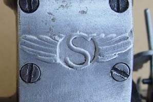
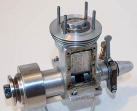
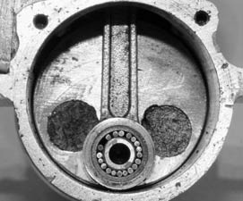
Exhaust ports on the three known examples all differ somewhat in size, and angle. Two have tapped holes to take an exhaust manifold. Further evidence of a one at a time build philosophy. The large transfer cover looks like it was a die cast component, and is solid and flat backed. The winged "S" remains something of an enigma, obviously in keeping with the Speedwell identity of the engine. Moving inside the engine the connecting rod is of interest being an I beam section alloy casting, with a large big end to take a roller bearing set up as per the Dooling 61.
|
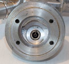
The crankshaft has as far as I can tell has a 3/8" or 1/2" dia main journal, with a full crank disc, with inserted lead counterbalancing. A hardened steel crank pin is pressed in to the web to run with the roller big end. I have not taken the shaft out, not wanting to disturb the bearings. Front bearing however is quite intriguing, as it appears to be white metalled and cast into the main bearing housing. It may be a close running seal? – perhaps there is a needle roller bearing behind it, or the more traditional ball races? The front bearing nose housing on the crankcase is quite large at 1-1/8" dia. A close fitting steel washer separates the front bearing from the split collet on the 5/16" BSF shaft end. |
|
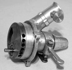
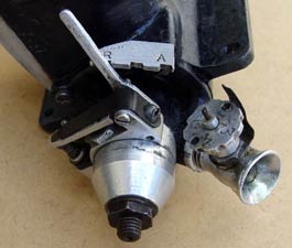
Moving to the back of the engine, the rear rotary disc is an all steel affair, and machined integral with the rear output shaft. A hardened steel driving pin is secured in the disc valve, which is well balanced with a series of peripheral holes drilled in its edge. It has a separate ignition cam locked in place via a collet on the output shaft. This being tightened in place with the bullet shaped blind nut fairing. The output end of the shaft could also drive an externally mounted magneto if required. Rear crankcase and induction housing is an alloy casting, which carries the contact breaker bracket, and screw in carburettor. The carb on my engine is a replacement item and not the original. The carb it appears was a neat fabrication of dural parts pressed, and held together. Finished off with a rather nice needle and jet screw control wheel, indexed and stamped with numbers, a typical Ken Robinson design feature.
 |
 |
 |
Overall, was the engine successful? With hindsight it is easy to be critical. It was a very interesting attempt to design and manufacture a competitive power unit for tether cars. Bearing in mind at the time it was not easy to obtain examples of the all conquering Doolings, McCoys, and Hornets from the US. Sadly the Speedwell did not feature as far as I can tell in any published competition wins. It was probably down on overall power output and performance, some mention of porous castings has also been suggested although not manifest on my example. Made in comparatively small numbers the engine was probably only circulated at local club level, with a few being sold further afield through Arthur Mullet’s shop. It quickly slipped into obscurity with the passing of the big 10cc racing cars, and the tether car sport in general. Ken’s move onto smaller diesel powered devices such as the R.T.D Special saw it relegated to the pages of history.
What’s in a name? I find the name Speedwell interesting given the date of the model engine's manufacture. This pre-dates the engine tuning experts Speedwell, famous for doing hot up conversions to Austin A35’s and the like, this kicked off in the early 1950’s. There was some similarity, with the logo being an S with a ½ wing.
Of course there was the early American car manufacturer from the 1907-14 period called Speedwell, but this again does not look to be a likely candidate. This does leave one plausible explanation, not for the name as such, more the winged S logo on the transfer cover.
|
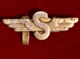
When my father was at Short Bros he was an active member of the Shorts model flying club. The club badge was in fact a winged S. The surviving example of the in house manufactured lapel badge shown is with dad's other model club badges from his pre-war model flying days. |
|
|
Ken Robinson was also believed to have been a member of the club and the similarity of design may give some clue to its origin.
It must be remembered that the above text is from my own personal observations of the engines, and information passed down to me by those that were there at the time, as such it can only ever be a snapshot of events of that interesting period in our modelling past.
©copyrightKenSmith2015